29 0024 ALPS, 29 0024 Datasheet - Page 3
29 0024
Manufacturer Part Number
29 0024
Description
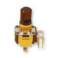
POTENTIOMETER, 100KB
Manufacturer
ALPS
Series
RK09r
Datasheet
1.29_0024.pdf
(5 pages)
Specifications of 29 0024
Track Resistance
100kohm
Track Taper
Linear
No. Of Turns
1
Resistance Tolerance
± 20%
Voltage Rating
20V
Power Rating
50mW
No. Of Gangs
1
Resistor Element
RoHS Compliant
Adjustment Type
Vertical
Potentiometer Mounting
PCB
Rohs Compliant
Yes


NOTE
MECHANICAL
ENDURANCE
ELECTRICAL
4.Residual
8. Robustness of shaft asainst end thrust ■
2. Operating temperature '-10 C-+60 C. 3. Storage temperature =-30 C~+70°C.
2. Operation torque
3. Shaft end stoo stren9th
4. Star t i ns toruaue
6. Play of shaft
7. Eccentricity of shaft
9. Robustness of shaft aeainst side thrust =
3. Rated voltage
5. 51 id ins noise
6. Insulation resistance : Greater than 100 Ma measured by 0. C. 250V.
7. Withstand voltaoe: More than I minute with an application of A. C 250 V.
8. Taper
5. Resistance to soldering heat
I-The items exceot above menjionedoitems shall meet or exceed JIS C 6443.
DATE
2. Rated power
1. Overall rotational angle ! 280°±5°
1. Total resistance : IOOkn±20X
I. -fro tat i o n a
3 seconds.
After soldering (less than 300° C and quicker than 3 seconds) there shall tie no
evidence of poor contact between resistance element and terminals, or any
physical damages as a result of the test.
The resistor shall be mounted by solder ins the mountino less on the panel,
and a side thrust of 250 of-cm at the end of the shaft shall be applied,
then the total Play of the shaft shall not exceed
The eccentricity of the root of shaft shall not exceed 0.35mm asainst the
center of
The shaft shall withstand asainst end thrust o! not less than 5 Kgf lor
The shaft shall withstand asainst side thrust of not less than 4 Kgf-cm lor
3 seconds on the end of the shaft at right ansles to the axis of the Shalt
after mounting the resistor by soldering.
The rated voltage shall be the voltase of D. C.
rated voltase exceeds the maximum working voltase given in the lot lowing,
however,
(commercial freauency .effective value ) corresoondim to the rated power
(dissipation), and be obtained from the folloiiins formula. When the obtained
APP0
Where
Maximum workine voltaee : 50 V A. C. .
I
CHKD
the mounting Position.
the maximumjiorkins voltase of the following shall be the rated voltage.
resistance between
■
E = /FT (V)
E : Rated voltase
P : Rated Dower (dissipation)
R : Nominal
lite
DSGO
between
■
■
:
: 8
= 0. 05 W
=
Set. 13. '$S
APP0.
S. A i tana
Less than 100 mV measured by method of JIS C 6443.
1
'■
5. 000 cycles rain.
SPECIFICATIONS
term. I&2.
total
: 10~80 gf-cm
: 3 Kof-cm MIN.
: lOOgf-cmMAX.
'
Sec.ii'ss
CHKD.
H. Sat oh
:
resistance
(V)
I ' I
I
terminals
r. Saitoh
term. 2&3
Set. 13. 'SI
DSGD.
ELECTRIC CO., LTD.
20 V 0. C.
I1
(ff)
(o)
or A. C.
TITLE
DOCUMENT NO.
W1 0 I 1 765M
0. 5 x I / 20 mm p-p.
••
I
300Q
I
max.
I
Related parts for 29 0024
Image
Part Number
Description
Manufacturer
Datasheet
Request
R

Part Number:
Description:
POTENTIOMETER, 10KB
Manufacturer:
ALPS
Datasheet:
Part Number:
Description:
POTENTIOMETER, 10KA
Manufacturer:
ALPS
Datasheet:
Part Number:
Description:
POTENTIOMETER, 10KA
Manufacturer:
ALPS
Datasheet:

Part Number:
Description:
POTENTIOMETER, 10KB
Manufacturer:
ALPS
Datasheet:
