29 0007 ALPS, 29 0007 Datasheet - Page 3
29 0007
Manufacturer Part Number
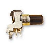
29 0007
Description
POTENTIOMETER, 10KA
Manufacturer
ALPS
Series
RK09r
Datasheet
1.29_0007.pdf
(5 pages)
Specifications of 29 0007
Track Resistance
10kohm
Track Taper
Log (Audio)
No. Of Turns
1
Resistance Tolerance
± 20%
Voltage Rating
20V
Power Rating
50mW
No. Of Gangs
1
Resistor Element
RoHS Compliant
Adjustment Type
Horizontal
Potentiometer Mounting
PCB
Rohs Compliant
Yes


SYMB
NOTE
MECHANICAL
ENDURANCE
ELECTRICAL
4.Residual
4. Starting toruque
2. Operating temperature
6.Insulation resistance : Greater than 100 Ma measured by D. C. 250V.
7. Withstand voltage1 More than I minute with an application of A. C. 250 V.
8. Taper
2. Operation
3. Shaft
5. Resistance to soldering heat
6. Play of shaft
7. Eccentricity of
8. Robustness of
9- Robustness of shaft against side thrust
I.The items except above mentionedoitems shall meet or exceed JIS C 6443.
DATE
2. Rated power
3- Rated voltage
5. Sliding noise
1.Overall
I.Total
1. ftotat ionaI
After soldering (Less than 300°C and quicker than 3 seconds) there shall be no
The eccentricity of
The shaft shall withstand against end thrust of not
3 seconds.
The shaft shall withstand against side thrust of not
3 seconds on the end of the shaft at right angles to the axis of the shaft
after mounting the resistor by soldering.
evidence of Poor contact
The resistor shall
and a side thrust of 250 »f-cm at the end of
center of
Physical damages as a result of the test.
then the total
'
The rated voltage shall
rated voltage exceeds the maximum working voltage given
however,
(commercial
(dissioat ion), and be obtained from the
APPO
Where
Maximum working voltage : 50 V A. C.
end stoo strength
resistance =
ill!
rotational angle : 280 15
CHKD
the mounting position.
toraue
the maximum working voltage of
resistance
life
E = fFT (V)
E = Rated voltage (V)
P : Rated oower (d issi oat ion)
R : Nominal total resistance
frequency .effective value
DSGD
between
Play of the shaft shal I not exceed
shaft aoainst end thrust
shaft
ature =-10 C~+60 C. 3. Storage temperature =-30 C~+70°C.
:
:
:
:
: A
be mounted by soldering
the root of shaft shall not exceed 0.35mm against the
See. 13.'SB
APPO.
S. Ailana
0. 05 W
IOk n ±208
Less than 100 mV measured by method of
:
between resistance element and terminals,
5.000 cycles nin.
SPECIFICATIONS
term. 142.
be the voltage
between
: 3 Kgf-cm MIN.
:
:
I
10-80 gf-cm
100 sf-cm MAX.
Set. 13. '3$
CHKD.
M. S3 lot)
ALPS ELECTRIC CO., LTD.
:
o
I
c
terminals
y. Saitoh
term. 2&3
Set. 13. 'SB
DSCD.
I
)
of D. C.
following
the following shall
corresponding
the mounting
:
.
:
the shaft shall
20 V D. C.
I
(W)
to)
or A. C.
TITLE
DOCUMENT
WI O I I 7 58M
0. 5 x L / 20 mm o-o.
formula.
:
less than 5 Kgf for
t
less than 4 Ksl-cm for
300Q
~
legs on the panel,
to
NO.
in
When
the rated Power
be applied,
the
max.
be the rated voltage.
the obtained
fol lotting,
JIS C 6443.
or any
Related parts for 29 0007
Image
Part Number
Description
Manufacturer
Datasheet
Request
R

Part Number:
Description:
POTENTIOMETER, 10KB
Manufacturer:
ALPS
Datasheet:
Part Number:
Description:
POTENTIOMETER, 10KA
Manufacturer:
ALPS
Datasheet:

Part Number:
Description:
POTENTIOMETER, 10KB
Manufacturer:
ALPS
Datasheet:
Part Number:
Description:
POTENTIOMETER, 100KB
Manufacturer:
ALPS
Datasheet:
