14810F0GJSX10103KA Vishay, 14810F0GJSX10103KA Datasheet - Page 3
14810F0GJSX10103KA
Manufacturer Part Number
14810F0GJSX10103KA
Description
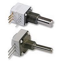
POTENTIOMETER SINGLE 0.5W 10K POTENTIOMETER SINGLE 0.5W 10K
Manufacturer
Vishay
Series
148r
Datasheet
1.14810F0GJSX10103KA.pdf
(5 pages)
Specifications of 14810F0GJSX10103KA
Resistors Element Type
RESISTANCE, TRACK
Power Rating
0.5W
Angle, Rotation Mechanical
300(DEGREE)
Diameter, Shaft
3.17MM
Temp, Op. Max
120(DEGREE C)
Rohs Compliant
YES


148, 149
Vishay Spectrol
www.vishay.com
104
LOCATING PEGS (Anti-Rotation Lug)
The locating peg is provided by a plate mounted on the bushing
and positioned by the module sides. Four set positions are
available, clock face orientation: 12, 3, 6, 9.
All 148, 149 bushings have a double flat. When panel mounting
holes have been punched accordingly, an anti-rotation lug is not
necessary.
RSID OPTION: ROTARY SWITCH MODULES
MODULES: RS ON/OFF SWITCH
RSI CHANGEOVER SWITCH
The position of each module is free.
RS and RSI rotary switches are housed in a standard 148, 149
module size 12.7 mm x 12.7 mm x 5.08 mm (0.5" x 0.5" x 0.2").
They have the same terminal styles as the assembled electrical
modules.
An assembly can comprise 1 or more switch modules.
Switch actuation is described as seen from the shaft end.
D:means actuation in maximum CCW position
The switch actuation travel is 25° with a total mechanical travel of
300° ± 5° and electrical travel of electrical module is 238° ± 10°.
RSID SINGLE POLE CHANGEOVER
In full CCW position, the contact is made between 3 and 2 and
open between 3 and 1. Switch actuation (CW direction) reverses
these positions.
9
12
6
3
L
1/2" (12.7 mm) Conductive Plastic and Cermet
Ø d
For technical questions, contact:
Potentiometers
Locating pegs are supplied in separate bags with nuts and
washers
ELECTRICAL DIAGRAM
Note
• Common
CODE
• Rotary switches
• Current up to 2 A
• SPDT: Single pole, changeover switch in CCW position - 3 pins
SWITCH SPECIFICATIONS
Switching Power Maximum
Switching Current Maximum
Maximum Current Through Element
Contact Resistance
Dielectric
Strength
Maximum Voltage Operation
Insulation Resistance Between Contacts
Life at P
Minimal Travel
Operating Temperature
C
sfer@vishay.com
A
B
max.
VERSION
Ø d mm
Ø d mm
Ø d mm
L mm
L mm
L mm
Terminal to Terminal
Terminal to Bushing
BUSHING
CCW POSITION
A, B
7.75
6.2
2
2
-
-
1
RSID
2
3*
BUSHING
7.75
13.5
Document Number: 57040
6.2
3.5
F
2
2
10 000 actuations
- 40 °C to + 85 °C
Revision: 01-Apr-09
0.25 A 250 V ν
0.5 A 30 V =
EFFECTIVE
1000 V
2000 V
HIGH PEG
62.5 VA ν
15 VA =
10
250 V ν
30 mΩ
30 V =
2 A
25°
6
0.7
0.7
1.1
-
-
-
MΩ
RMS
RMS
Related parts for 14810F0GJSX10103KA
Image
Part Number
Description
Manufacturer
Datasheet
Request
R

Part Number:
Description:
357-036-542-201 CARDEDGE 36POS DL .156 BLK LOPRO
Manufacturer:
Vishay
Datasheet:
Part Number:
Description:
357-036-542-201 CARDEDGE 36POS DL .156 BLK LOPRO
Manufacturer:
Vishay
Datasheet:
Part Number:
Description:
357-036-542-201 CARDEDGE 36POS DL .156 BLK LOPRO
Manufacturer:
Vishay
Datasheet:
Part Number:
Description:
357-036-542-201 CARDEDGE 36POS DL .156 BLK LOPRO
Manufacturer:
Vishay
Datasheet:
Part Number:
Description:
357-036-542-201 CARDEDGE 36POS DL .156 BLK LOPRO
Manufacturer:
Vishay
Datasheet:
Part Number:
Description:
357-036-542-201 CARDEDGE 36POS DL .156 BLK LOPRO
Manufacturer:
Vishay
Datasheet:
Part Number:
Description:
357-036-542-201 CARDEDGE 36POS DL .156 BLK LOPRO
Manufacturer:
Vishay
Datasheet:
Part Number:
Description:
357-036-542-201 CARDEDGE 36POS DL .156 BLK LOPRO
Manufacturer:
Vishay
Datasheet:
Part Number:
Description:
357-036-542-201 CARDEDGE 36POS DL .156 BLK LOPRO
Manufacturer:
Vishay
Datasheet:
Part Number:
Description:
357-036-542-201 CARDEDGE 36POS DL .156 BLK LOPRO
Manufacturer:
Vishay
Datasheet:
Part Number:
Description:
357-036-542-201 CARDEDGE 36POS DL .156 BLK LOPRO
Manufacturer:
Vishay
Datasheet:
Part Number:
Description:
357-036-542-201 CARDEDGE 36POS DL .156 BLK LOPRO
Manufacturer:
Vishay
Datasheet:
Part Number:
Description:
357-036-542-201 CARDEDGE 36POS DL .156 BLK LOPRO
Manufacturer:
Vishay
Datasheet:
Part Number:
Description:
357-036-542-201 CARDEDGE 36POS DL .156 BLK LOPRO
Manufacturer:
Vishay
Datasheet:
Part Number:
Description:
357-036-542-201 CARDEDGE 36POS DL .156 BLK LOPRO
Manufacturer:
Vishay
Datasheet: