6637S-1-102 Bourns Inc., 6637S-1-102 Datasheet
6637S-1-102
Manufacturer Part Number
6637S-1-102
Description
POT, PRECISION, 1KOHM, 10%, 1W
Manufacturer
Bourns Inc.
Series
6637r
Datasheet
1.6637S-1-502.pdf
(2 pages)
Specifications of 6637S-1-102
Track Resistance
1kohm
Track Taper
Linear
No. Of Turns
1
Resistance Tolerance
± 10%
Power Rating
1W
Termination Type
Solder
Adjustment Type
Shaft
Temperature Coefficient
± 500ppm/°C
Resistance
1 KOhms
Tolerance
10 %
Termination Style
Lug
Number Of Turns
1
Shaft Type
Slotted
Shaft Length
22.23 mm
Shaft Diameter
3.17 mm
Dimensions
22.23 mm Dia. x 12.7 mm L
Product
Precision Potentiometers
Filter Terminals
Solder
Rohs Compliant
Yes
Potentiometer Mounting
Bushing
No. Of Gangs
1
Lead Free Status / RoHS Status
Lead free / RoHS Compliant
Available stocks
Company
Part Number
Manufacturer
Quantity
Price
Company:

Part Number:
6637S-1-102
Manufacturer:
BOURNS
Quantity:
20 000


Standard Resistance Range ................................................................................... 1 K to 100 K ohms
Total Resistance Tolerance .........................................................................................................±10 %
Independent Linearity ...................................................................................................................±1 %
Effective Electrical Angle ...................................................................................................... 340 ° ±3 °
End Voltage ................................................................................................................0.5 % maximum
Output Smoothness ...................................................................................................0.1 % maximum
Dielectric Withstanding Voltage (MIL-STD-202, Method 301)
Power Rating (Voltage Limited By Power Dissipation or 300 VAC, Whichever is Less)
Insulation Resistance (500 VDC) .................................................................1,000 megohms minimum
Resolution ................................................................................................................Essentially infi nite
Operating Temperature Range ................................................................................ -40 °C to +125 °C
Storage Temperature Range ................................................................................... -65 °C to +125 °C
Temperature Coeffi cient Over Storage Temperature Range ..........................±500 ppm/°C maximum
Vibration ........................................................................................................................................15 G
Shock ............................................................................................................................................50 G
Load Life ................................................................................................................ 1,000 hours, 1 watt
Rotational Life (No Load) .........................................................................10,000,000 shaft revolutions
Moisture Resistance (MIL-STD-202, Method 106)
IP Rating ....................................................................................................................................... IP 40
Stop Strength ................................................................................................53 N-cm (75 oz.-in.) min.
Mechanical Angle ...............................................................................................................Continuous
Torque (Starting & Running) ..............................................................0.40 N-cm (0.5 oz.-in.) maximum
Shaft Runout .............................................................................................. 0.025 mm (0.001 in.) T.I.R.
Shaft End Play .............................................................................................. 0.13 mm (0.005 in.) T.I.R.
Shaft Radial Play .......................................................................................... 0.13 mm (0.005 in.) T.I.R.
Backlash ....................................................................................................................... 0.1 º maximum
Weight ........................................................................................................................................ 16 gm
Terminals ..................................................................................................................... Rear turret type
Soldering Condition
Marking ................................ Manufacturer’s name and part number, resistance value and tolerance,
Ganging (Multiple Section Potentiometers) .................................................................. 1 up maximum
Hardware .................................. One lockwasher (H-37-2) and one mounting nut (H-38-2) is shipped
1
At room ambient: +25 °C nominal and 50 % relative humidity nominal, except as noted.
Electrical Characteristics
Sea Level .............................................................................................................750 VAC minimum
+70 °C..................................................................................................................................... 1 watt
+125 °C................................................................................................................................... 0 watt
Environmental Characteristics
Wiper Bounce .......................................................................................... 0.1 millisecond maximum
Total Resistance Shift ..............................................................................................±5 % maximum
Voltage Ratio Shift ................................................................................................±0.5 % maximum
Total Resistance Shift ............................................................................................±10 % maximum
Total Resistance Shift ............................................................................................±10 % maximum
Total Resistance Shift ............................................................................................±15 % maximum
Mechanical Characteristics
Mounting.............................................................................170-200 N-cm (15-18 lb.-in.) maximum
Manual Soldering ............................... 96.5Sn/3.0Ag/0.5Cu solid wire or no-clean rosin cored wire
Wave Soldering........................................................ 96.5Sn/3.0Ag/0.5Cu solder with no-clean fl ux
Wash processes ................................................................................................. Not recommended
1
1
1
linearity tolerance, wiring diagram, and date code.
Features
■
■
■
■
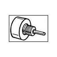
6637 - Precision Potentiometer
Bushing mount
Excellent resolution
High rotational life
Non-standard features and specifi cations available
370 °C (700 °F) max. for 3 seconds
260 °C (500 °F) max. for 5 seconds
with each potentiometer.
Customers should verify actual device performance in their specifi c applications
*RoHS Directive 2002/95/EC Jan 27, 2003 including Annex.
(.443
BOLDFACE LISTINGS ARE IN STOCK AND READILY
AVAILABLE THROUGH DISTRIBUTION.
FOR SERVO MOUNT VERSION AND OTHER OPTIONS
CONSULT FACTORY.
6637
7/8 " (22 mm) DIA.
11.25
22.23
(7/8)
DIA.
Part Number
6637S-1-102
6637S-1-502
6637S-1-103
Product Dimensions
Recommended Part Numbers
NOTE: SHAFT SUPPORTED BY FRONT SLEEVE BEARING.
Specifi cations are subject to change without notice.
CCW
.015)
.38
1
(.062)
(1/8)
1.57
3.18
CLOCKWISE
2
10.317 + .000/- .051
(7/8
(.4062+.000/-.002)
22.23
3/8-32 UNEF-THD
CW
WIPER
3
(3/8
9.53
1/32)
(.1248+.0000/-.0003)
(.032)
3.170 + .000/-.008
.79
Resistance (Ω)
2
.81
30
TYP.
1/32)
.79
10,000
1
1,000
5,000
WIDE X
SHAFT SLOT
3
3
CW
DIA.
(.032)
45
X
CHAMFER
.81
(.010)
(.19)
4.83
.25
DIA.
DEEP
5
R
Related parts for 6637S-1-102
Image
Part Number
Description
Manufacturer
Datasheet
Request
R

Part Number:
Description:
PRECISION POT - 7/8" (22MM) 1-TURN CP
Manufacturer:
Bourns Inc.
Datasheet:

Part Number:
Description:
Manufacturer:
Bourns, Inc.
Datasheet:
Part Number:
Description:
11mm Potentiometer
Manufacturer:
Bourns, Inc.
Datasheet:
Part Number:
Description:
Manufacturer:
Bourns, Inc.
Datasheet:
Part Number:
Description:
Manufacturer:
Bourns, Inc.
Datasheet:
Part Number:
Description:
Manufacturer:
Bourns, Inc.
Datasheet:
Part Number:
Description:
5/16 Round Trimming Potentiometer
Manufacturer:
Bourns, Inc.
Datasheet:
Part Number:
Description:
4100R Series: Thick Film Moulded DIPs - Resistor Networks
Manufacturer:
Bourns, Inc.
Datasheet:
Part Number:
Description:
PROTECTOR - SINGLE BIDIRECTIONAL
Manufacturer:
Bourns, Inc.
6637S-1-102 Summary of contents
Page 1
... WIPER CCW CLOCKWISE Recommended Part Numbers Part Number Resistance (Ω) 6637S-1-102 1,000 6637S-1-502 5,000 6637S-1-103 10,000 BOLDFACE LISTINGS ARE IN STOCK AND READILY AVAILABLE THROUGH DISTRIBUTION. FOR SERVO MOUNT VERSION AND OTHER OPTIONS CONSULT FACTORY. *RoHS Directive 2002/95/EC Jan 27, 2003 including Annex. ...
Page 2
Precision Potentiometer Panel Thickness Dimensions 10.41 ± .08 DIA. (.410 ± .003) Anti-rotation pin hole is shown at six o'clock position for reference only. The actual location is determined by the customer's application. Refer to the front view ...