77F221J-RC Bourns Inc., 77F221J-RC Datasheet
77F221J-RC
Manufacturer Part Number
77F221J-RC
Description
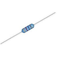
CHOKE, 220UH, 155MA, 5%, 3MHZ
Manufacturer
Bourns Inc.
Datasheet
1.77F101J-TR-RC.pdf
(2 pages)
Specifications of 77F221J-RC
Inductance
220µH
Inductance Tolerance
± 5%
Dc Resistance Max
5ohm
Dc Current Rating
155mA
Self Resonant Frequency
3MHz
Q Factor
70
Inductor Case Style
Axial Leaded
No. Of Pins
2
Lead Free Status / RoHS Status
Lead free / RoHS Compliant
Available stocks
Company
Part Number
Manufacturer
Quantity
Price

Part Number:
77F221J-RC
Manufacturer:
BOURNS/伯恩斯
Quantity:
20 000


*RoHS Directive 2002/95/EC Jan 27 2003 including Annex.
Specifi cations are subject to change without notice.
Customers should verify actual device performance in their specifi c applications.
Electrical Specifi cations (@ 25 °C)
77F1R0K-RC
77F1R2K-RC
77F1R5K-RC
77F1R8K-RC
77F2R2K-RC
77F2R7K-RC
77F3R3K-RC
77F3R9K-RC
77F4R7K-RC
77F5R6K-RC
77F5R8K-RC
77F8R2K-RC
Bourns Part
77F100K-RC
77F120K-RC
77F150K-RC
77F180K-RC
77F220K-RC
77F270K-RC
77F330J-RC
77F390J-RC
77F470J-RC
77F560J-RC
77F680J-RC
77F820J-RC
77F101J-RC
77F121J-RC
77F151J-RC
77F181J-RC
77F221J-RC
77F271J-RC
77F331J-RC
77F391J-RC
77F471J-RC
77F561J-RC
77F681J-RC
77F821J-RC
77F102J-RC
No.
1000
(μH)
100
120
150
180
220
270
330
390
470
560
680
820
1.0
1.2
1.5
1.8
2.2
2.7
3.3
3.9
4.7
5.6
6.8
8.2
10
12
15
18
22
27
33
39
47
56
68
82
Inductance
Tol. (%)
±10
±10
±10
±10
±10
±10
±10
±10
±10
±10
±10
±10
±10
±10
±10
±10
±10
±10
±5
±5
±5
±5
±5
±5
±5
±5
±5
±5
±5
±5
±5
±5
±5
±5
±5
±5
±5
Min.
45
50
50
55
55
60
65
65
70
70
75
80
85
75
70
65
60
55
55
50
45
40
40
35
30
70
70
70
70
65
65
65
60
60
55
55
50
Q
Frequency
Features
■
■
■
■
77F Series Conformal Coated RF Choke
(MHz)
0.796
0.796
0.796
0.796
0.796
0.796
0.796
0.796
0.796
0.796
0.796
0.796
0.796
Test
25.2
7.96
7.96
7.96
7.96
7.96
7.96
7.96
7.96
7.96
7.96
7.96
7.96
2.52
2.52
2.52
2.52
2.52
2.52
2.52
2.52
2.52
2.52
2.52
Formerly
Current rating up to 920 mA
Inductance range: 1.0 μH to 1,000 μH
RoHS compliant*
J. W .Miller
(MHz)
Min.
SRF
2.25
2.10
1.95
1.85
1.40
157
144
131
121
110
100
9.9
7.6
6.3
6.3
6.3
6.2
5.7
5.3
4.8
3.8
3.5
3.3
3.0
2.8
2.6
2.4
94
86
80
74
68
53
45
34
20
14
model
DCR
Max.
0.17
0.18
0.20
0.22
0.24
0.25
0.30
0.35
0.40
0.45
0.50
0.52
0.65
0.70
0.75
0.80
0.90
1.00
1.10
1.20
1.30
1.50
1.80
2.00
2.50
12.0
14.0
20.0
3.0
4.0
4.5
5.0
6.0
6.5
7.5
8.5
9.5
(Ω)
(mA)
920
880
830
790
750
720
670
640
620
590
550
530
500
480
460
430
410
390
370
350
340
320
305
290
275
185
175
165
155
145
137
133
126
120
113
105
100
Idc
Applications
■
■
■
Temperature Rise ................ 35 °C at Idc
Operating Temperature
Storage Temperature
Dielectric Strength ................... 500 Vrms
Core .............................................. Ferrite
Wire ............................. Polyester copper
Terminal Coating .............Sn-Ag-Cu alloy
Coating .................................Epoxy resin
Packaging ..... 5000 pcs. per 14-inch reel
Model
Value Code
Packaging Code
Compliance Code
Example:
General Specifi cations
Materials
DC/DC converters
Power supplies
General use
How to Order
Electrical Schematic
............................... -55 °C to +105 °C
............................... -55 °C to +105 °C
(See table)
TR = 5000 pcs./14-inch reel
RC = RoHS compliant*
77F102J-TR-RC = 1000 μH packaged
5000 pcs./14-inch reel.
77F 151J - TR - RC
Related parts for 77F221J-RC
Image
Part Number
Description
Manufacturer
Datasheet
Request
R

Part Number:
Description:
Power Inductors 220uH 5%
Manufacturer:
Bourns Inc.
Datasheet:

Part Number:
Description:
Manufacturer:
Bourns, Inc.
Datasheet:
Part Number:
Description:
11mm Potentiometer
Manufacturer:
Bourns, Inc.
Datasheet:
Part Number:
Description:
Manufacturer:
Bourns, Inc.
Datasheet:
Part Number:
Description:
Manufacturer:
Bourns, Inc.
Datasheet:
Part Number:
Description:
Manufacturer:
Bourns, Inc.
Datasheet:
Part Number:
Description:
5/16 Round Trimming Potentiometer
Manufacturer:
Bourns, Inc.
Datasheet:
Part Number:
Description:
4100R Series: Thick Film Moulded DIPs - Resistor Networks
Manufacturer:
Bourns, Inc.
Datasheet:
Part Number:
Description:
PROTECTOR - SINGLE BIDIRECTIONAL
Manufacturer:
Bourns, Inc.
77F221J-RC Summary of contents
Page 1
... 45 77F560J-RC 56 ±5 40 77F680J-RC 68 ±5 40 77F820J-RC 82 ±5 35 77F101J-RC 100 ±5 30 77F121J-RC 120 ±5 70 77F151J-RC 150 ±5 70 77F181J-RC 180 ±5 70 77F221J-RC 220 ±5 70 77F271J-RC 270 ±5 65 77F331J-RC 330 ±5 65 77F391J-RC 390 ±5 65 77F471J-RC 470 ±5 60 77F561J-RC 560 ±5 60 77F681J-RC 680 ±5 55 77F821J-RC 820 ± ...
Page 2
... MIN. 0.64 (0.025) DIMENSIONS: 10.41 (0.41) MAX. 3.99 MAX. (0.157) MM (INCHES) Customers should verify actual device performance in their specifi c applications. Typical Part Marking - EIA Color Code 1st & 2nd Significant Color Figure Multiplier Tolerance Silver 0.01 ±10 % Gold 0.1 ± ...