FLT-100V10 Murata Power Solutions Inc, FLT-100V10 Datasheet - Page 3
FLT-100V10
Manufacturer Part Number
FLT-100V10
Description
POWER LINE FILTER, 10A
Manufacturer
Murata Power Solutions Inc
Datasheet
1.FLT-100V10.pdf
(7 pages)
Specifications of FLT-100V10
Input Voltage Min
0VDC
Peak Reflow Compatible (260 C)
No
Output Current
10A
Output Current 1
10A
Leaded Process Compatible
No
Input Voltage Max
100VDC
Mounting Type
PC Board Surface Mount
Lead Free Status / RoHS Status
Contains lead / RoHS non-compliant


Performance/Functional Specifi cations
Typical @ T
➀ +25°C, 20lfm (natural convection).
➁ +60°C, 20lfm air fl ow (natural convection).
Input Voltage Range:
Average Current @ +25°C: ➀
Average Current @ +60°C: ➁
Resistance Per Leg:
FLT-100V20:
Isolation Voltage Input to GND
Isolation Voltage Output to GND
Differential-Mode Insertion Loss
Common-Mode Insertion Loss
Operating Case Temperature
MTBF @ 100°C Case
Storage Temperature
Case Material
Case Dimensions:
Pin Material
Pin Diameter:
Pin Length
Weight:
Lead Temperature
Input Voltage Range
Isolation Voltage Input to GND
Isolation Voltage Output to GND
Operating Case Temperature
Storage Temperature
FLT-100V10
FLT-100V20
FLT-100V10
FLT-100V20
FLT-100V10
FLT-100V20
FLT-100V10
FLT-100V20
FLT-100V10
FLT-100v20
FLT-100V10
FLT-100V20
Soldering, 10 seconds
FLT-100V10:
@ 25°C
@ –40°C
@ +125°C
@ 25°C
@ –40°C
@ +125°C
A
= +25°C under nominal line voltage, balanced "full-load" conditions, unless noted.
Absolute Maximum Ratings
Dynamic Characteristics
Environmental
Physical
Input
100 Volts maximum
10 Amps maximum
20 Amps maximum
10 Amps maximum
20 Amps maximum
9.5mΩ
7.6mΩ
11.8mΩ
4.8mΩ
4mΩ
6.3mΩ
1500Vdc minimum
1500Vdc minimum
See Ordering Guide
See Ordering Guide
–40 to +100°C
2,856,374 hours
2,521,681 hours
–55 to +125°C
Plastic, UL 94V-0 rating
1" x 2" x 0.5" (25.4 x 50.8 x 12.7mm)
1.6" x 2" x 0.5" (40.6 x 50.8 x 12.7mm)
Brass, solder coated
0.031" (0.787mm)
0.040" (1.016mm)
See Part Number Structure
1.28 ounces (36.3 grams)
2.16 ounces (61.2 grams)
+300°C
100 Volts
1500Vdc minimum
1500Vdc minimum
–40 to +100°C
–55 to +125°C
www.murata-ps.com
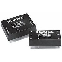
Description
The FLT-100V series of passive fi lters are optimized to reduce both common-
mode and differential-mode noise on both input and output lines of switching
DC/DC converters. The FLT-100V10 is rated for 10A of continuous current while
the FLT-100V20 is rated for 20A.
Differential-mode and Common-mode Noise
Designers who are faced with reducing conducted emissions in DC/DC
applications must address both differential-mode and common-mode noise.
Differences measured between the two input lines of the DC/DC converter are
classifi ed as differential noise. The dominant contribution to differential noise is
the switching action of the DC/DC converter. Consequently, the majority of noise
will be seen at the converter’s switching frequency and it’s harmonics. The
FLT-100V series fi lter uses a mylar, self healing, 100Vdc rated input capacitor
connected between the two input lines (traditionally referred to as “X” capaci-
tors), in conjunction with the leakage inductance of the common mode chokes to
attenuate the low-frequency differential noise. In addition to the fi lter, a low-ESR
input capacitor (C1 of Figure 4) is also recommended at the input to the DC/DC
to provide a low source impedance and additional noise attenuation.
See typical performance curves for differential-mode insertion loss performance.
Common –mode noise is measured as variations between the input lines (in
common) with respect to the Ground pin. Common-mode noise is gener-
ally in the high frequency spectrum (>10MHz) and originates in the switching
components of the DC/DC converter. A capacitor from each line to the ground
pin (referred to as “Y” capacitors), connected between the two common mode
chokes, provides attenuation of this unwanted common-mode noise. This
ground pin should be connected to a relatively quiet chassis ground point inde-
pendent from the DC/DC converter case connection. Note that a noisy chassis
ground can inadvertently introduce common noise into the system. Some
DATEL DC/DC converters are designed with an internal input-to-outptut capaci-
tor to reduce common-mode noise generated from within the converter. In addi-
tion, common-mode noise can be reduced with the addition of external ceramic
capacitors of 0.1μF to 1.0μF (C2 thru C4 of Figure 4) installed from inputs and
outputs to a shield plane connected to the DC/DC case; safety standards may
limit the size of these capacitors for some applications. See typical performance
curves for common-mode insertion loss performance.
FLT-100V series fi lters incorporate an internal, multi-layer fi lm polymer capacitor
between the input lines for differential-mode noise fi ltering. This telecom/data-
com preferred capacitor provides electrical stability under both AC and DC
current loads. The capacitors insulation resistance tends to improve under the
stresses of heat and voltage. A typical ESR of 6 milli-OHMs @ 500kHz, pro-
vides the necessary low impedance for high frequency input current handling.
T E C H N I C A L
Filter Modules, 100Vdc, 10 Amp and 20 Amp
Technical enquiries email: sales@murata-ps.com, tel:
N O T E S
Differential/Common-Mode Filters
MMP_FLT10-20-Series.B03 Page 3 of 7
FLT Series
+1 508 339 3000
Related parts for FLT-100V10
Image
Part Number
Description
Manufacturer
Datasheet
Request
R

Part Number:
Description:
EMI/RFI Suppressors & Ferrites 100Vin 20A Common-Mode Filters
Manufacturer:
Murata Power Solutions Inc
Part Number:
Description:
EMI/RFI Suppressors & Ferrites 100V Input 10A Rated SHORT PINS 0.110
Manufacturer:
Murata Power Solutions Inc
Part Number:
Description:
EMI/RFI Suppressors & Ferrites 100V Input 10A Rated SHORT PINS 0.145
Manufacturer:
Murata Power Solutions Inc

Part Number:
Description:
ROUND FLOPPY CABLES, COLOR: BLUE, SIZE: 24 , FEATURES: HIGH PERFORMANCE, MOLDED, INCREASES THE COOLING IN THE SYSTEM
Manufacturer:
MCM
Part Number:
Description:
ROUND IDE CABLES, COLOR: YELLOW, SIZE: 18 , FEATURES: HIGH PERFORMANCE, INCREASE THE COOLING IN SYSTEM WITH THESE PREMIUM CABLES
Manufacturer:
MCM
Part Number:
Description:
ROUND IDE CABLES, COLOR: YELLOW, SIZE: 24 , FEATURES: HIGH PERFORMANCE, MOLDED, INCREASES THE COOLING IN THE SYSTEM
Manufacturer:
MCM
Part Number:
Description:
ROUND IDE CABLES, COLOR: BLACK, SIZE: 24 , FEATURES: HIGH PERFORMANCE, MOLDED, INCREASES THE COOLING IN THE SYSTEM
Manufacturer:
MCM
Part Number:
Description:
ROUND FLOPPY CABLES, COLOR: BLUE, SIZE: 18 , FEATURES: HIGH PERFORMANCE, INCREASE THE COOLING IN SYSTEM WITH THESE PREMIUM CABLES
Manufacturer:
MCM


Part Number:
Description:
Transformers 5Vin 5Vout 200mA 4000Vdc 1:1.33 turn
Manufacturer:
Murata Power Solutions Inc
Datasheet:
Part Number:
Description:
POWER SUPPLY
Manufacturer:
Murata Power Solutions Inc
Datasheet:

Part Number:
Description:
DPM LED MINI 2VDC 3.5DIG LP RED
Manufacturer:
Murata Power Solutions Inc
Datasheet:

Part Number:
Description:
CONV DC/DC 1W 5VIN 5VOUT SIP SGL
Manufacturer:
Murata Power Solutions Inc
Datasheet:

Part Number:
Description:
CONV DC/DC 1W 5VIN 3.3V SIP SGL
Manufacturer:
Murata Power Solutions Inc
Datasheet: