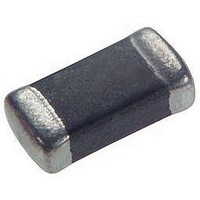
EXCML16A270U Panasonic, EXCML16A270U Datasheet - Page 7

EXCML16A270U
Manufacturer Part Number
EXCML16A270U
Description
FERRITE CHIP BEAD, 4A, 25%
Manufacturer
Panasonic
Series
EXCMLr
Datasheet
1.EXC3BB102H.pdf
(8 pages)
Specifications of EXCML16A270U
Impedance
27ohm
Dc Resistance Max
6mohm
Dc Current Rating
4000mA
Ferrite Mounting
SMD
Ferrite Case Style
0603
Reel Quantity
4000
Termination Type
SMD
Test Frequency
100MHz
Filter Terminals
SMD
Rohs Compliant
Yes
Package / Case
0603
Resistance
0.006ohm
Lead Free Status / RoHS Status
Lead free / RoHS Compliant
Available stocks
Company
Part Number
Manufacturer
Quantity
Price
Company:
Part Number:
EXCML16A270U
Manufacturer:
PANASONI
Quantity:
43 400
Company:
Part Number:
EXCML16A270U
Manufacturer:
PANASONIC
Quantity:
60 000
Company:
Part Number:
EXCML16A270U
Manufacturer:
PANASONIC
Quantity:
216 300
■
Recommendations and precautions are described below.
<Repair with hand soldering>
● Preheat with a blast of hot air or similar method. Use a soldering iron with a tip temperature of 350 °C or less. Solder
● Never touch this product with the tip of a soldering iron.
■
The following are precautions for individual products. Please also refer to the precautions common to EMI Filters,
Fuses, and Sensors(MR Elements) shown on page EX2 of this catalog.
1. With regard to fl ow soldering, consult with our sales person in advance.
2. Use rosin-based fl ux or halogen-free fl ux.
3. For cleaning, use an alcohol-based cleaning agent. Before using any other type, consult with our sales per son
4. Do not apply shock to Chip Bead Cores (hereafter called the bead cores) or pinch them with a hard tool (e.g.
5. Store the bead cores in a location with a temperature ranging from -5 °C to +40 °C and a rel a tive humidity of
6. Use the bead cores within a year (EXC3B Type: within half a year) after the date of the out go ing in spec tion
Design and specifi cations are each subject to change without notice. Ask factory for the current technical specifi cations before purchase and/or use.
Should a safety concern arise regarding this product, please be sure to contact us immediately.
Recommended Soldering Conditions
● Please contact us for additional information when used in conditions other than those specifi ed.
● Please measure the temperature of the terminals and study every kind of solder and printed circuit board
each electrode for 3 seconds or less.
Recommended Land Pattern Dimensions in mm (not to scale)
in advance.
pliers and tweezers). Otherwise, their bodies may be chipped, affecting their per for mance.
Excessive mechanical stress may damage the bead cores. Handle with care.
40 % to 60 %, where there are no rapid changes in temperature or humidity.
indicated on the packages.
Safety Precautions
for solderability before actual use.
<Recommended reflow soldering temperature>
✽ Refl ow soldering shall be performed a maximum of two times.
(Sn-3Ag-0.5Cu)
For soldering
Rising temperature I
For lead-free
(Sn-37Pb)
soldering
Solder
C
Rising temperature I
The normal time
The normal time
for preheating
for preheating
Preheating
30 s to 60 s
30 s to 60 s
A
Time (min.)
Rising temperature II
B
140 °C to 160 °C
150 °C to 170 °C
60 s to 120 s
60 s to 120 s
Preheating
heating
Main
EXC3B
EXCML45A910H
EXCML32A680U
EXCML20A390U
EXCML16A270U
EXCCL4532U1
EXCCL3225U1
EXCCL3216U1
Part Number
Rising temperature II
Preheating to 200 °C
Preheating to 210 °C
Gradual
cooling
20 s to 40 s
20 s to 40 s
H
0.8 to 1.2
2.6 to 3
1.6 to 2
0.6 to 1
0.8 to 1
270
260
250
240
230
220
210
200
1.7
1.7
Main heating
A
3
235±10 °C
0
250
Peak
Peak
10
+10
– 5
to reflow soldering heat
The limit of resistance
°C
20
5.5 to 6.5
2 to 2.6
30
Time (s)
4 to 5
3 to 4
2 to 3
5.4
4.1
4.1
200 °C to 100 °C
210 °C to 100 °C
B
Gradual cooling
Chip Bead Cores
1 °C to 4 °C/s
1 °C to 4 °C/s
40
50
60
1.2 to 1.6
1.2 to 1.6
1 to 1.2
0.8 to 1
0.8 to 1
70
2.8
2.1
1.2
C
Feb. 2006
(mm)


