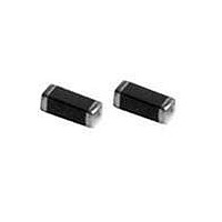
2512066017Y0 Fair-Rite, 2512066017Y0 Datasheet - Page 22

2512066017Y0
Manufacturer Part Number
2512066017Y0
Description
FERRITE BEAD, 1206, 0.25OHM, 200mA
Manufacturer
Fair-Rite
Datasheet
1.2512066017Y0.pdf
(160 pages)
Specifications of 2512066017Y0
Impedance
600ohm
Dc Resistance Max
0.25ohm
Dc Current Rating
350mA
Ferrite Mounting
SMD
Ferrite Case Style
1206
Current Rating
200mA
No. Of Pins
2
Impedance Tolerance
± 0.25%
Product
Chip Ferrite Beads
Tolerance
25 %
Maximum Dc Current
350 mAmps
Maximum Dc Resistance
0.25 Ohms
Operating Temperature Range
- 55 C to + 125 C
Package / Case
1206 (3216 metric)
Termination Style
SMD/SMT
Lead Free Status / RoHS Status
Lead free / RoHS Compliant
Lead Free Status / RoHS Status
Lead free / RoHS Compliant, Lead free / RoHS Compliant
- Current page: 22 of 160
- Download datasheet (3Mb)
Chip Inductors
60
F air-Rite Prod ucts Cor p.
Phone:
Chip Inductor
Part Number Sytem: Example 2212061R2K7F
Multi-Layer
Multi-Layer chip inductors have complimented our line of chip components. These chip inductors have
silk-screened windings on a ferrite or non- magnetic ceramic body which after sintering forms a monolithic
structure which is a self shielding, closed magnetic unit.
Chip inductors come in two types, with a ferrite body and with a non-magnetic ceramic core. Both types
provide excellent solderability and heat resistance for either flow or reflow soldering processes.
Both chip inductor types are used in tuned applications and for energy storage devices for frequencies in the
hundreds of MHz into the GHz range.
• Chip inductors are supplied taped and reeled, if required bulk packed parts can be supplied. See table on the next page for
• Chip inductors are 100% tested for a toleranced inductance and minimum Q at specified test frequencies.
• Suggested land patterns are in accordance to the latest revision of IPC-7351.
• Chip inductors have plated contacts, 100% tin over a nickel undercoating.
• Suggested temperature soldering profile is shown page 28.
• Recommended storage and operating temperature range is -40
• The Fair-Rite Products CD-ROM has a number of typical performance curves for the ferrite and ceramic multi-layer chip inductors.
• The new “Chip Inductor Kit” (part number 0199000035) contains a cross section of both types of multi-layer chip inductors. See page 68.
22
tape and reel particulars.
(888) FAIR RITE / (845) 895-2055 • FAX: (888) FERRITE / (845) 895-2629
(888) 324-7748
1206
Package
Size
R = Decimal point for µH (>99nH)
N = Decimal point for nH
(4N7 = 4.7nH = 0.0047µH)
(47N = 47nH = 0.047µH)
(R22 = 0.22µH)
(2R2 = 2.2µH)
Inductance
(888) 337 -7483
Code
1R2
0
C to + 85
Inductance
Tolerance
S = ± 0.3nH
J = ± 5%
K = ± 10%
M = ± 20%
• www.fair-rite.com
• E-Mail: ferrites@fair-rite.com
PO Box J, One Commercial Row, Wallkill, NY 12589-0288
0
K
C.
6 = Bulk Packed
7 = T&R (7")
8 = T&R (13")
Packaging
Code
7
For general signal usage
For high frequency usage
F = Ferrite Body
C = Ceramic Body
15th Edition
Material
Code
F
Related parts for 2512066017Y0
Image
Part Number
Description
Manufacturer
Datasheet
Request
R

Part Number:
Description:
EMI/RFI Suppressors & Ferrites LF Z=95OHM @ 100MHz
Manufacturer:
Fair-Rite

Part Number:
Description:
EMI/RFI Suppressors & Ferrites Z=94ohms @ 10MHz
Manufacturer:
Fair-Rite
Datasheet:

Part Number:
Description:
EMI/RFI Suppressors & Ferrites LF Z=47OHM @ 100MHz
Manufacturer:
Fair-Rite
Datasheet:

Part Number:
Description:
EMI/RFI Suppressors & Ferrites Z=300 @ 100MHz
Manufacturer:
Fair-Rite
Datasheet:

Part Number:
Description:
EMI/RFI Suppressors & Ferrites Z=365 OHM @ 100 MHz
Manufacturer:
Fair-Rite
Datasheet:

Part Number:
Description:
EMI/RFI Suppressors & Ferrites LF Z=133OHM @ 100MHz T/R
Manufacturer:
Fair-Rite
Datasheet:

Part Number:
Description:
EMI/RFI Suppressors & Ferrites Z=132 OHM @ 100MHz
Manufacturer:
Fair-Rite
Datasheet:

Part Number:
Description:
EMI/RFI Suppressors & Ferrites Z=33 OHM @ 100MHz
Manufacturer:
Fair-Rite
Datasheet:

Part Number:
Description:
EMI/RFI Suppressors & Ferrites LF Z=78OHM @ 25MHz
Manufacturer:
Fair-Rite
Datasheet:

Part Number:
Description:
FERRITE CORE, CYLINDRICAL
Manufacturer:
Fair-Rite
Datasheet:

Part Number:
Description:
FERRITE BEAD, SMD, 350mOHM, 400mA
Manufacturer:
Fair-Rite
Datasheet:

Part Number:
Description:
FERRITE CORE, CYLINDRICAL
Manufacturer:
Fair-Rite
Datasheet:

Part Number:
Description:
FERRITE BEAD, SMD, 1.4mOHM, 5A
Manufacturer:
Fair-Rite
Datasheet:

Part Number:
Description:
CHIP BEAD,Ferrite
Manufacturer:
Fair-Rite
Datasheet:


