CTS13105X9040A2P Vishay, CTS13105X9040A2P Datasheet - Page 17
CTS13105X9040A2P
Manufacturer Part Number
CTS13105X9040A2P
Description
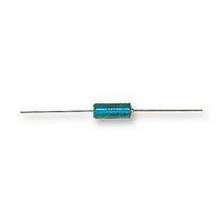
CAPACITOR, 1UF 40V CAPACITOR, 1UF 40V
Manufacturer
Vishay
Series
CTS13r
Datasheet
1.CTS13105X9040A2P.pdf
(19 pages)
Specifications of CTS13105X9040A2P
Capacitance
1UF
Voltage Rating, Dc
40V
Capacitor Dielectric Type
TANTALUM ELECTROLYTIC
Tolerance,
10%
Tolerance, -
10%
Temp, Op. Min
-55(DEGREE C)
Temp, Op. Max
55(DEGREE
Rohs Compliant
YES
Available stocks
Company
Part Number
Manufacturer
Quantity
Price
Company:

Part Number:
CTS13105X9040A2PE3
Manufacturer:
ATMEL
Quantity:
1 492


PERFORMANCE CHARACTERISTICS
(Continued)
10. Humidity test:
Table 7
Table 8
Typical values of charge-discharge current (per above test
conditions)
12. Insulation test:
13. Lead pull test:
Document Number: 42073
Revision: 02-Nov-09
CAPACITANCE CHANGE
DC LEAKAGE CURRENT
DISSIPATION FACTOR
CAPACITANCE CHANGE
DC LEAKAGE CURRENT
After 56 days (1350 h) at + 40 °C, 90 % to 95 % of relative
humidity (per IEC 68-2-3) with no voltage applied,
capacitors shall meet the requirements in table 7 below.
For capacitors with insulating sleeves, a DC voltage
of 100 V shall be applied for one minute between the
case of the capacitor and a metal “V” block in intimate
contact with the insulating sleeve. The insulating
resistance measured in these conditions shall be at least
100 MΩ.
Leads shall withstand the following test (IEC 68-2-2):
Tensile stress of 5N (cases A and B) or 10N
(cases C and D) for 10 s in any direction
Two cosecutive rotations of 180°
One bend in each direction
DISSIPATION FACTOR
RATED VOLTAGE
U
6.3
.
R
10
16
25
40
50
63
(V)
CHARGE-DISCHARGE CURRENT
Within ± 3 % of initial value
Within ± 5 % of initial value
Within initial requirement
Within initial requirement
Within initial requirement
Within initial requirement
at + 25 °C - Table 3
at + 25 °C - Table 2
at + 25 °C - Table 3
at + 25 °C -Table 2
at + 25 °C
100
126
(A)
13
20
32
50
80
Hermetically Sealed, Axial-Lead
For technical questions, contact:
to CECC Specifications
GUIDE TO APPLICATION
1. A-C Ripple current:
2. A-C Ripple voltage:
3. AC Ripple current or voltage derating factor:
4. Power dissipation:
The calculations are summarized on the graphs page 59
The
determined from the formula:
where,
P = Power Dissipation in W at + 25 °C as given below
R
specified frequency.
The
determined from the formula:
giving the maximum available ripple voltage as a function
of frequency.
However, the sum of the peak AC voltage plus the DC
voltage shall not exceed the rated DC voltage at + 85 °C
of the capacitor. The sum of the negative peak AC voltage
plus the DC voltage shall not allow a voltage reversal
exceeding 15 % of the rated DC voltage.
If these capacitors are to be operated at temperatures
above + 25 °C, the permissible rms ripple current or
voltage shall be calculated using the derating factors in the
table below:
Power dissipation will be affected by the heat sinking
capability of the mounting surface. Non-sinusoidial ripple
current may produce heating effects which differ from
those shown in the following table. It is important that the
equivalent Irms value be established when calculating
permissible operating levels.
ESR
tantalum@vishay.com
where,
Z = The capacitor Impedance at the specified
TEMPERATURE
CASE CODE
= The capacitor Equivalent Series resistance at the
maximum
maximum
V
I
rms
rms
+ 125 °C
+ 25 °C
+ 55 °C
+ 85 °C
frequency.
C
D
A
B
=
=
--------------- -
R
---------------- -
R ESR
CTS1, CTS13, 749DX
ESR
allowable
allowable
P
P
×
Z
ripple
ripple
POWER DISSIPATION
Vishay Sprague
DERATING FACTOR
AT + 25 °C (W)
voltage
current
0.115
0.145
0.185
0.225
1.0
0.8
0.6
0.4
www.vishay.com
shall
shall
be
be
70
Related parts for CTS13105X9040A2P
Image
Part Number
Description
Manufacturer
Datasheet
Request
R

Part Number:
Description:
357-036-542-201 CARDEDGE 36POS DL .156 BLK LOPRO
Manufacturer:
Vishay
Datasheet:
Part Number:
Description:
357-036-542-201 CARDEDGE 36POS DL .156 BLK LOPRO
Manufacturer:
Vishay
Datasheet:
Part Number:
Description:
357-036-542-201 CARDEDGE 36POS DL .156 BLK LOPRO
Manufacturer:
Vishay
Datasheet:
Part Number:
Description:
357-036-542-201 CARDEDGE 36POS DL .156 BLK LOPRO
Manufacturer:
Vishay
Datasheet:
Part Number:
Description:
357-036-542-201 CARDEDGE 36POS DL .156 BLK LOPRO
Manufacturer:
Vishay
Datasheet:
Part Number:
Description:
357-036-542-201 CARDEDGE 36POS DL .156 BLK LOPRO
Manufacturer:
Vishay
Datasheet:
Part Number:
Description:
357-036-542-201 CARDEDGE 36POS DL .156 BLK LOPRO
Manufacturer:
Vishay
Datasheet:
Part Number:
Description:
357-036-542-201 CARDEDGE 36POS DL .156 BLK LOPRO
Manufacturer:
Vishay
Datasheet:
Part Number:
Description:
357-036-542-201 CARDEDGE 36POS DL .156 BLK LOPRO
Manufacturer:
Vishay
Datasheet:
Part Number:
Description:
357-036-542-201 CARDEDGE 36POS DL .156 BLK LOPRO
Manufacturer:
Vishay
Datasheet:
Part Number:
Description:
357-036-542-201 CARDEDGE 36POS DL .156 BLK LOPRO
Manufacturer:
Vishay
Datasheet:
Part Number:
Description:
357-036-542-201 CARDEDGE 36POS DL .156 BLK LOPRO
Manufacturer:
Vishay
Datasheet:
Part Number:
Description:
357-036-542-201 CARDEDGE 36POS DL .156 BLK LOPRO
Manufacturer:
Vishay
Datasheet:
Part Number:
Description:
357-036-542-201 CARDEDGE 36POS DL .156 BLK LOPRO
Manufacturer:
Vishay
Datasheet:
Part Number:
Description:
357-036-542-201 CARDEDGE 36POS DL .156 BLK LOPRO
Manufacturer:
Vishay
Datasheet: