30-174 IDEAL, 30-174 Datasheet - Page 56
30-174
Manufacturer Part Number
30-174
Description
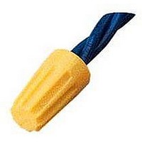
CLOSED END SPLICE, 17/64IN, TWIST-ON YEL
Manufacturer
IDEAL
Datasheet
1.30-071.pdf
(62 pages)
Specifications of 30-174
Connector Type
Closed End Splice
Insulator Color
Yellow
Termination Method
Twist-On
Wire Size (awg)
18-12
Insulator Material
Thermoplastic
Color
Yellow
Lead Free Status / RoHS Status
na


Specifications
Center-to-Center Spacing: .75 in. CL: 16 circuits per foot.
Voltage Rating: Blocks meet 600V creepage and clearance requirements of NEMA, UL and CSA for general industrial control equipment and
panelboards. Withstand voltages greatly in excess of IEEE switchgear standards for 750V.
Ampacity: Fuse blocks, 30A
Fuse Size: Any 13/32 in. x 1-1/2 in. ferrule-type cartridge fuse up to 30A, indicating or non-indicating, which meets MIL. Spec. F-15160 is
recommended.
Phenolic Fuse Blocks
I
I
I
I
I
I
I
I
I
I
Catalog Number
Mounting Style
Ampacity
Contact Type
Screw Type
Wire Range (AWG)
Wire Strip Length
Housing Material
Contact Material
Screw Material
Maximum Service Temperature
Breakdown Voltage AC, 60Hz
Dielectric Strength (RH40% at sea level)
UL High Voltage Arc Testing (in./min.)
Water Absorption (24 hrs. % weight gain)
Flammability
Chemical Resistance
Radiation Resistance (ergs g
A-56
Provide in-line circuit protection for any circuit or group of circuits
Three contact styles for terminated or unterminated wire are conservatively rated to 30A
Remove, check and replace fuses safely and quickly – switch-action fuse blocks open
circuits before fuse can be removed or installed
Good circuit density when mounted adjacently – 91 circuits per 6 foot length
Use in high temperature applications – phenolic housing withstands temperatures
up to 302°F (150°C)
Flat base models for surface mounting, dovetail base models for standard channel
Only one end section needed per block assembly
Open or close several circuits simultaneously – holes in puller handles allow use of nylon “ganging” rods
Readily identifiable circuits – mark directly on white, matte-surface puller assembly, marking tab on block or use removable marking tape
Sections snap-fit with Heavy Duty and Intermediate Heavy Duty Blocks
www.idealindustries.com
Direct Mount
(Flat Base)
351
Binding Head
Strap Screw
-1
#22 to #8
C)
10-32
30A
—
Channel Mount
(Dovetail Base)
0351
hydrocarbons and ketones (per ASTM D543)
Resistance to acids, alkalies and aliphatic
300V/mil thickness (per ASTM D149)
Phenolic, Filled, Flame retardant
Direct Mount
(Flat Base)
0.45% (per ASTM D570)
358
94V-1 (per UL94)
150°C (302°F)
2.7 x 10
Head w/Clamp
Copper alloy
Steel Plated
Strap Clamp
#18 to #8
.49 - .58
8-32 Pan
8400V
1/2 in.
30A
7
min.
Channel Mount
(Dovetail Base)
0358
Direct Mount
(Flat Base)
352
Tubular Screw
Set Screw
WIRE RANGE: Solid or Stranded
Tubular Screw, Cat. No. 362 and 0362
1 #4 AWG, 1 #6 AWG, 1 or 2 #8 AWG, 1 to 4 #10 AWG, 1 to 5 #12 AWG, 1 to 6 #14
AWG, 1 to 6 #16 AWG, 1 to 8 #18 AWG
#18 - #8
LR25557
1/4-28
1/2 in.
30A
Channel Mount
(Dovetail Base)
0352
E63810
(Direct Mount)
End-Section
330
—
—
—
—
—
(ChannelMount)
End-Section
1-800-435-0705 for Customer Service
0330
—
—
—
—
—
Related parts for 30-174
Image
Part Number
Description
Manufacturer
Datasheet
Request
R

Part Number:
Description:
CLOSED END SPLICE, 17/64IN, TWIST-ON YEL
Manufacturer:
IDEAL
Datasheet:


Part Number:
Description:
Connector; Wire-Nut; 20 to 16 AWG; 600 V (max); orange
Manufacturer:
Ideal Industries
Datasheet:
Part Number:
Description:
Disconnect; push-in; for Luminaire lighting only; 3 A max
Manufacturer:
Ideal Industries


Part Number:
Description:
Pushbutton Switch,STRAIGHT,SPST,OFF-(ON),SOLDER Terminal
Manufacturer:
Grayhill Inc
Datasheet:

Part Number:
Description:
Standard LED - Through Hole White Water Clear
Manufacturer:
Everlight Electronics CO., LTD
Part Number:
Description:
Standard LED - Through Hole Bluish Green
Manufacturer:
Everlight Electronics CO., LTD
Part Number:
Description:
Standard LED - Through Hole White
Manufacturer:
Everlight Electronics CO., LTD
Part Number:
Description:
Standard LED - Through Hole Hyper Red
Manufacturer:
Everlight Electronics CO., LTD
Part Number:
Description:
Standard LED - Through Hole Hyper Red
Manufacturer:
Everlight Electronics CO., LTD