25-140-Y Cinch Connectors, 25-140-Y Datasheet
25-140-Y
Specifications of 25-140-Y


Related parts for 25-140-Y


25-140-Y Summary of contents
Page 1
COMMERCIAL Barrier Blocks Circular Mini DIN BNC Jones Plugs Edge Connectors ...
Page 2
... When looking for time reliability to solve your commercial interconnect needs, look no further than Cinch Connectors. Whether it's a Jones Plug and Socket, Barrier Block, Edge Card, Mini Din plug, or our newest addition, the 75Ω ...
Page 3
... Interposing barriers between terminals yield higher electrical ratings and provide additional protection against frayed wire shorting. ■ A wide variety of barrier blocks makes it possible to select the combination of mechanical and electrical characteristics that best meet the exact requirements of your application. ■ A wide selection of optional terminals and fanning strips permits the equipment designer to choose the method of termination most suitable for his environmental specifications and manufacturing requirements ...
Page 4
... Voltage Rating Size Terminal 250 Volts 15 Amps #16 3750 250 Volts 20 Amps #14 5000 250 Volts 30 Amps #10 7500 250 Volts 40 Amps #10 10,000 250 Volts 50 Amps #8 12,500 250 Volts 70 Amps #6 54,000 250 Volts 15 Amps #14 3750 600 Volts 15 Amps #16 3750 600 Volts 20 Amps #14 5000 600 Volts ...
Page 5
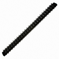
... Barrier Blocks Series 140 Electrical Characteristics Voltage Rating: 250 VAC RMS maximum Current Rating: 15 Amps maximum Maximum Watts Per Terminal: 3750 Mechanical Characteristics Maximum Wire Size: #16 AWG Recommended Tightening Torque: 9 lb.-in. Dimensions Ordering Information No. of Terminals Call Toll Free: 1 (800) 323-9612 .375 Density, 5-40 x 3/16" ...
Page 6
... Catalog No. Y-140 3/4W-140 W-140 2-5 “W” Terminals Catalog No. 1-140-W 2-140-W 3-140-W 4-140-W 5-140-W 6-140-W 7-140-W 8-140-W 9-140-W 10-140-W 11-140-W ...
Page 7
... MS-9-140-Y MS-10-140 MS-10-140-Y MS-11-140 MS-11-140-Y MS-12-140 MS-12-140-Y MS-13-140 MS-13-140-Y MS-14-140 MS-14-140-Y MS-15-140 MS-15-140-Y MS-16-140 MS-16-140-Y MS-17-140 MS-17-140-Y MS-18-140 MS-18-140-Y MS-19-140 MS-19-140-Y MS-20-140 MS-20-140-Y MS-21-140 MS-21-140-Y MS-22-140 MS-22-140-Y MS-23-140 MS-23-140-Y MS-24-140 MS-24-140-Y MS-25-140 MS-25-140-Y 2-6 “Y” Terminal Marketed exclusively through distribution. ...
Page 8
... Barrier Blocks Series 141 Electrical Characteristics Voltage Rating: 250 VAC RMS maximum Current Rating: 20 Amps maximum Maximum Watts Per Terminal: 5000 Mechanical Characteristics Maximum Wire Size: #14 AWG Recommended Tightening Torque: 12 lb.-in. Dimensions Ordering Information No. of Terminals Call Toll Free: 1 (800) 323-9612 .438 Density, 6-32 x 1/4" ...
Page 9
Barrier Blocks Series 141 Solder Terminal Options Dimensions “Y” Terminals Ordering Information No. of Terminals Catalog No. 1 1-141-Y 2 2-141-Y 3 3-141-Y 4 4-141-Y 5 5-141-Y 6 6-141-Y 7 7-141-Y 8 8-141-Y 9 9-141-Y 10 10-141-Y 11 11-141-Y 12 ...
Page 10
DURA-CON ® Barrier Blocks High Reliability Series 141 All-Plastic Marker Strips Dimensions Standard 2 Ordering Information No. of Terminals Use ...
Page 11
... Barrier Blocks Series 142 Electrical Characteristics Voltage Rating: 250 VAC RMS maximum Current Rating: 30 Amps maximum Maximum Watts Per Terminal: 7500 Mechanical Characteristics Maximum Wire Size: #10 AWG Recommended Tightening Torque: 16 lb.-in. Dimensions Ordering Information No. of Terminals Call Toll Free: 1 (800) 323-9612 .563 Density, 8-32 x 5/16" ...
Page 12
Barrier Blocks Series 142 Solder Terminal Options Dimensions “Y” Terminals Ordering Information No. of Terminals Catalog No 10-142-Y 11 11-142-Y 12 12-142-Y 13 13-142-Y 14 14-142-Y 15 15-142-Y 16 16-142-Y ...
Page 13
DURA-CON ® Barrier Blocks High Reliability Series 142 All-Plastic Marker Strips Dimensions Standard 2 Ordering Information No. of Terminals Use Standard Marker Strips ...
Page 14
... Density, 10-32 x 5/16" Barrier Blocks BH Screw, Open Bottom, Series 150 Double Row Electrical Characteristics Voltage Rating: 250 VAC RMS maximum Current Rating: 40 Amps maximum Maximum Watts Per Terminal: 10,000 Mechanical Characteristics Maximum Wire Size: #10 AWG Recommended Tightening Torque: 20 lb.-in. ...
Page 15
Barrier Blocks Series 150 Marker Strips Dimensions Standard .688 TYP (17.46) Ordering Information No. of Terminals Accessories None Available for 150 Series. .688 Density, 10-32 x 5/16" BH Screw, Open ...
Page 16
... Barrier Blocks Series 151 Electrical Characteristics Voltage Rating: 250 Volts maximum Current Rating: 50 Amps maximum Maximum Watts Per Terminal: 12,500 Mechanical Characteristics Maximum Wire Size: #8 Recommended Tightening Torque: 40 lb.-in. Dimensions Ordering Information No. of Terminals Catalog No. 1 1-151 2 2-151 3 3-151 4 4-151 5 5-151 ...
Page 17
... Barrier Blocks Series 152 Electrical Characteristics Voltage Rating: 250 Volts maximum Current Rating: 70 Amps maximum Maximum Watts Per Terminal: 54,000 Mechanical Characteristics Maximum Wire Size: #6 Recommended Tightening Torque: 75 lb.-in. Dimensions Ordering Information No. of Terminals Catalog No. 1 1-152 2 2-152 3 3-152 4 4-152 5 5-152 ...
Page 18
... Barrier Blocks Series 164 Electrical Characteristics Voltage Rating: 250 Volts maximum Current Rating: 15 Amps maximum Maximum Watts Per Terminal: 3750 Mechanical Characteristics Maximum Wire Size: #14 Recommended Tightening Torque: 12 lb.-in. Dimensions Ordering Information No. of Terminals Call Toll Free: 1 (800) 323-9612 .375 Density, 6-32 x 5/16" ...
Page 19
Barrier Blocks Series 164 Solder Terminal Options Dimensions “Y” Terminals Ordering Information No. of Terminals .375 Density, 6-32 x ...
Page 20
DURA-CON ® Barrier Blocks High Reliability Series 164 All-Plastic Marker Strips Dimensions Standard 2 Ordering Information No. of Terminals ...
Page 21
... Marker Strip Dim. (in) Catalog No. ...
Page 22
... Marker Strip Catalog No. MSX-2-541 MSX-3-541 MSX-4-541 MSX-5-541 MSX-6-541 MSX-7-541 MSX-8-541 MSX-9-541 MSX-10-541 MSX-11-541 MSX-12-541 MSX-13-541 MSX-14-541 MSX-15-541 MSX-16-541 MSX-17-541 MSX-18-541 ...
Page 23
... MSX-8-542 6.036 MSX-9-542 6.599 MSX-10-542 7.162 MSX-11-542 7.725 MSX-12-542 8.288 MSX-13-542 8.851 MSX-14-542 9.414 MSX-15-542 9.977 MSX-16-542 10.540 MSX-17-542 11.103 MSX-18-542 11.666 MSX-19-542 12.229 MSX-20-542 12.792 MSX-21-542 13.355 MSX-22-542 13.918 MSX-23-542 14.481 MSX-24-542 15.044 MSX-25-542 15.607 MSX-26-542 Marketed exclusively through distribution. ...
Page 24
... Barrier Blocks Series 176 Electrical Characteristics Voltage Rating: 250 Volts maximum Current Rating: 15 Amps maximum Maximum Watts Per Terminal: 3750 Mechanical Characteristics Maximum Wire Size: 16 AWG Recommended Tightening Torque: 16 lb.-in. Dimensions L M Ordering Information With Mounting Ears No. of Catalog No. Terminals .125 Tail Lgth ...
Page 25
... .063 1.60 .146 3.71 .094 .078 1.98 .152 3.86 .125 .094 2.39 .177 4.50 .125 Marketed exclusively through distribution 2.39 3.18 3. 2.31 2.62 3. 2.39 3.18 3.18 ...
Page 26
Barrier Blocks Accessories Quick Clamp Terminals Simplifies engaging of wires to barrier blocks. Wire is inserted into flared opening and screw is tightened. Screws are brass binder head type with nickel plating. Terminals are brass with tin plating. Includes two ...
Page 27
... Barrier Block Accessories ■ Minimize wiring errors. ■ Available in straight and right-angle styles. ■ Available with cable clamp hole on right or left side, designated by “L” or “R” at end of catalog number. ■ Cable clamp hole for securing cable/wires with lacing twine or ty-wrap. ...
Page 28
Barrier Block Accessories Catalog Numbers and Dimensions for Fanning Strips for 140 Series Terminal Blocks Straight Type Dimensions Catalog No. 6-160-R Ordering Information No. of Terminals Catalog No. 2 2-160-R 3 3-160-R 4 4-160-R 5 5-160-R 6 6-160-R 7 7-160-R ...
Page 29
DURA-CON ® Barrier Block High Reliability Accessories All-Plastic Catalog Numbers and Dimensions for Fanning Strips for 140 Series Terminal Blocks, Continued Right-Angle Type Dimensions 2 Ordering Information Call Toll Free: 1 (800) 323-9612 Fanning Strips Fanning Strips Catalog No. 6-160A-R ...
Page 30
Barrier Block Accessories Catalog Numbers and Dimensions for Fanning Strips for 141 Series Terminal Blocks Straight Type No. of Terminals Catalog No. Catalog No. 2 2-161-R 2-161-L 3 3-161-R 3-161-L 4 4-161-R 4-161-L 5 5-161-R 5-161-L 6 6-161-R 6-161-L 7 ...
Page 31
Barrier Block Accessories Catalog Numbers and Dimensions for Fanning Strips for 142 Series Barrier Blocks Straight Type Ordering Information No. of Terminals Catalog No. 2 2-162-R 3 3-162-R 4 4-162-R 5 5-162-R 6 6-162-R 7 7-162-R 8 8-162-R 9 9-162-R ...
Page 32
... Accessories Materials Insulation Material rated XPC, chocolate Contact Material: Steel Contact Plating: Cadmium Mechanical Characteristics Mounting Hole: .140" (3.56mm) diameter Strip Dimension: .0625" (1.59mm) thick x .375" (9.53mm) wide Lug Density: .375" (9.53mm) Ordering Information Mounting Lug Type Used In Position Catalog No. Centers ...
Page 33
... Jones Plugs/Sockets Series 300 ■ Solder lug terminals with .093" x .062" (2.36mm x 1.57mm) wiring holes. ■ Two-contact "Jones" connector is round, all others are rectangular. ■ For use in cable-to-panel and cable-to-cable applications. ■ Designed for light and medium duty. ■ Plug prongs are .156" (3.96mm) wide and .047" (1.19mm) thick. ...
Page 34
Jones Plugs/Sockets Series 300 Polarizing Patterns - 300 Series Multiple Density Solder Eyelet Marketed exclusively through distribution. Call Toll Free: 1 (800) 323-9612 2-37 ...
Page 35
... in mm 1.016 25.81 .750 19.05 .781 19.84 1.000 25.40 1.031 26.19 1.000 25.40 1.281 32.54 1.000 25.40 1.578 40.08 1.000 25.40 1.266 32.16 1.250 31.75 1.516 38.51 1.250 31.75 1.641 41.68 1.375 34.93 1.953 49.61 1.375 34.93 2.266 57.56 1.375 34.93 2 ...
Page 36
... M Polarizing in mm Pin See note - NO 1.250 31.75 NO .938 23.81 NO 1.250 31.75 14 1.562 39.69 14 1.875 47.63 14 2.188 55 ...
Page 37
... 13.11 1.750 44.45 19.46 1.750 44.45 19.46 1.750 44. 19.46 2.250 57.15 25.81 2.250 57.15 Marketed exclusively through distribution. E Max. mm 18.26 12.70 19.05 19.05 -- 19.05 25.40 ...
Page 38
... 1.016 25.81 1.016 25.81 1.016 25.81 1.016 25.81 1.016 25.81 1.016 25.81 1.016 25.81 2-41 P Polarizing Pin 41.28 NO 49.23 NO 57.15 NO 65.10 14 73.03 14 80.98 14 88. 2.000 50.80 2 ...
Page 39
... S-306-RP N/A N/A N 1.500 38.10 1.750 1.500 38.10 1.750 1.500 38.10 1.750 1.500 38.10 1.750 -- -- -- 2.000 50.80 2.250 2.000 50.80 2.250 2- Max 44.45 1.350 34.29 44.45 1.350 34.29 44.45 1.350 34.29 44.45 1.350 34. 57.15 1.850 46.99 57.15 1.850 46.99 Marketed exclusively through distribution. ...
Page 40
... Polarizing in mm Pin 2.547 64.69 NO 2.859 72.62 NO 3.172 80.57 NO 3.484 88.49 14 3.797 96.44 14 4.109 104.38 14 4.422 112. 2.125 53.98 2.438 61.93 2.750 69.85 3.062 77.77 3.376 85.75 3.688 93.68 4.000 101.60 Marketed exclusively through distribution. Call Toll Free: 1 (800) 323-9612 2 ...
Page 41
... 36.91 1.125 28.58 50.80 1.438 36.53 58.75 1.438 36.53 66.68 1.438 36.53 74.63 1.438 36.53 82.55 1.438 36 ...
Page 42
... Cable Opening Polarizing in mm Pin .563 14.30 NO .563 14.30 NO .625 15.88 NO .625 15.88 14 .625 15.88 14 .750 19.05 14 .750 19.05 17 Marketed exclusively through distribution. Call Toll Free: 1 (800) 323-9612 2 mm 7.95 6.35 9.53 11.13 -- 12.70 14.30 ...
Page 43
... Cable Opening 1.795 45.59 .563 14.30 2.107 53.52 .563 14.30 2.420 61.47 .625 15.88 2.732 69.39 .625 15.88 3.045 77.34 .625 15.88 3.357 85.27 .750 19.05 3.670 93.22 .750 19.05 2-46 E ± .031 “D” Cable Opening (.79mm .375 9.53 .359 9.12 ...
Page 44
... Marketed exclusively through distribution. Call Toll Free: 1 (800) 323-9612 2 Pin -- -- -- -- -- ...
Page 45
... Call Toll Free: 1 (800) 323-9612 [.050” (1.27mm) Density Multiple Density Solder Cup/Wire Solder Eyelet ...
Page 46
... Polarized to prevent wrong-way insertion. ■ Plugs have projecting flat blades, sockets have recessed twin bellows. ■ Cable clamps of zinc and clear irridite-plated steel are used for strain relief. ■ Bifurcated bellows socket contact provides four individual flexing surfaces for maximum contact with the blade. ...
Page 47
... Multiple Density Solder Eyelet Less Angle Bracket Socket Socket 14.29 .656 16.67 25.40 1.094 27.78 36.51 1.531 38.89 47.63 1.969 50.01 58.74 2.406 61.12 69.85 1.844 46.83 2-51 Marketed exclusively through distribution. Call Toll Free: 1 (800) 323-9612 ...
Page 48
... Multiple Density Solder Cup/Wire Solder Eyelet D-Microminiature] With Angle Bracket Catalog No. Socket S-2402-AB S-2404-AB S-2406-AB S-2408-AB S-2410-AB S-2412-AB Socket 14.29 .656 16.67 25.40 1.094 27.78 36.51 1.531 38.89 47.63 1.969 50.01 58.74 2.406 61.12 69.85 2.844 72.24 2-52 Marketed exclusively through distribution. ...
Page 49
... S-2402-SB S-2404-SB S-2406-SB S-2408-SB S-2410-SB S-2412- 1.062 26.99 1.766 1.500 38.10 1.234 1.938 49.23 1.672 2.375 60.33 2.109 2.813 71.45 2.547 3.250 82.55 2.984 2-53 R. Max. mm 19.45 31.34 42.47 53.57 64.69 75.80 Marketed exclusively through distribution. Call Toll Free: 1 (800) 323-9612 2 ...
Page 50
... Catalog No. Socket S-2402-DB S-2404-DB S-2406-DB S-2408-DB S-2410-DB S-2412-DB Socket 1.750 44.45 1.313 2.188 55.58 1.750 2.625 57.53 2.188 3.063 77.79 2.625 3.500 88.90 3.063 3.938 100.03 3.500 2-54 Plug or Socket M mm 33.35 44.45 55.58 66.68 77.80 88.90 Marketed exclusively through distribution. ...
Page 51
... With Hood & 90° Clamp Socket C Cable Opening 1.375 34.93 .375 1.375 34.93 .438 1.375 34.93 .438 1.344 34.13 .563 1.344 34.13 .563 1.312 33.34 .625 2-55 mm 9.53 11.11 11.11 14.29 14.29 15.88 Marketed exclusively through distribution. Call Toll Free: 1 (800) 323-9612 2 ...
Page 52
... With Hood & 180° Clamp Catalog No. Socket S-2402-CCT S-2404-CCT S-2406-CCT S-2408-CCT S-2410-CCT S-2412-CCT L Cable Opening .625 15.88 .313 1.062 26.99 .438 1.500 38.10 .438 1.937 49.21 .563 2.375 60.33 .563 2.813 71.45 .625 2-56 mm 7.94 11.11 11.11 14.29 14.29 15.88 Marketed exclusively through distribution. ...
Page 53
... .813 20.64 1.156 29.37 1.250 31.75 1.156 29.37 1.688 42.86 1.156 29.37 2.125 53.98 1.156 29.37 2.563 65.10 1.156 29.37 3.000 76.20 1.156 29. .938 23.81 1 ...
Page 54
... Circular Mini DIN Plugs ■ Contact positions and 8. ■ Pre-assembled with standard shielded cable lengths; consult factory for other lengths. ■ Molded-in strain relief. ■ Cable and overmold available in standard colors: black or beige. ■ Contacts available with gold over nickel. ■ Shielding system designed to meet FCC requirements for EMI/RFI suppression. ...
Page 55
Circular Mini DIN Plugs Dimensions 3-Contact 4-Contact 6-Contact Ordering Information: (NOTE: One meter = 39.62 inches.) For cable assemblies with plug on one end. Plug features contacts with Option 1 plating (gold flash over nickel). Cable No. of Length Contacts ...
Page 56
... Circular Mini DIN Plugs ■ Individual components available for cable assembly with overmolding. ■ Plug insulator available with contact positions and 8. ■ Seamless shield case is crimped to cable shield; designed to meet FCC requirements for EMI/RFI suppression. ■ One-piece shield case - no extra ferrules or shields required with Cinch Shield Crimp Tools. ■ ...
Page 57
... Pneumatic Crimp Tool Overview of Assembly Steps • Prepare multi-conductor cable. • Crimp contacts onto individual conductors using tool MDT-P25 or tool MDT-P35. • Insert contact with conductor into insulator using tool MDT-P41 or have insertion tool MDT-P28 with insulator locating vice MDT-P29. • Insert insulator into the shield case using tool MDT-P34 or MDT-P30. ...
Page 58
... Dip solder tails on .200" (5.08mm) row centers double readout. ■ Bifurcated semi-bellows contacts for added contact reliability. ■ Ideal for applications involving vibration or board irregularities. ■ Contact positions: 12, 15, 18, 20, 22, 25, 28, 30, 31, 36, 37, 40, 43, 44, 49, 50, 52, 60, 70, AT, and XT. ■ Accepts .062" (1.59mm) thick PC boards. ...
Page 59
... Mounting Holes Catalog No. 50-12SN-11 50-15SN-11 50-18SN-11 - 50-20SN-11 50-22SN-11 50-25SN-11 50-28SN-11 50-30SN-11 50-31SN-11 - 50-36SN-11 50-37SN-11 50-40SN-11 50-43SN-11 50-44SN-11 50-49SN-11 50-50SN-11 ...
Page 60
... CARDCON ™ Edge Connector Commercial ■ Dip solder tails single readout and double readout on .140" (3.56mm) row centers or .200" (5.08mm) row centers. ■ Solder eyelet, single readout and double readout on .200" (5.08mm) row centers. ■ Available with unique tails for PC board retention; holds the connector firmly on the board during wave soldering operations. ■ ...
Page 61
... Less Mounting Ears .128 Mounting Hole Pos./Cont. Catalog No. Catalog No. Dip solder tails, double readout, .140" (3.55mm) row spacing, .125" (3.18mm) long 6/12 50-12SN-4 50-12SN-2 10/20 50-20SN-4 50-20SN-2 12/24 50-24SN-4 50-24SN-2 15/30 50-30SN-4 ...
Page 62
... Edge Connector High Reliability ■ Dip solder tails, single readout, .156" (3.96mm) long or .234" (5.94mm) long. ■ Dip solder tails, double readout, .156" (3.96mm) or .234" (5.94mm) long on .200" (5.08mm) row spacing, or .125" (3.18mm) long on .140" (3.56mm) row spacing. ■ Solder eyelet, single readout and double readout on .200" (5.08mm) row spacing. ...
Page 63
... With Plain Mounting Holes Dimensions No Pos./Cont 1.100 27.94 10 1.724 43.79 12 2.036 51.71 15 2.504 63.60 18 2.972 75.49 20 3.286 83.46 22 3.596 91.34 25 4.067 103. 1.239 31.47 1.531 38.80 1.864 47.35 2.156 54.76 2.177 55.30 2.469 62.71 2.645 67.18 2.937 74.60 3.114 79.10 3.406 86 ...
Page 64
... Call Toll Free: 1 (800) 323-9612 [.050” (1.27mm) Density .156" (3.96mm) Density Dip Solder Cup/Wire Solder/Solder Eyelet D-Microminiature] .128" (3.25mm) Mounting Hole Dip Solder Tails Dip Solder Tails .156" (3.96mm) Long .234" (5.94mm) Long Catalog No. Catalog No. 50-6H-10 50-6S-10 ...
Page 65
... Edge Connector High Reliability ■ Solder terminations, double readout. ■ Bifurcated bellows type contacts. ■ Contact positions: 6, 10, 12, 15, 18, 22, and 25. ■ Accepts .062" (1.59mm) thick double-sided PC boards. Insulation Material: Diallyl phthalate, green Contact Material: Beryllium copper Contact Plating: 30µin. select gold over 50µin. nickel in the contact areas, 10µ ...
Page 66
... Ordering Information No. of Pos./Cont. 6/12 10/20 12/24 15/30 18/36 22/44 25/50 .156" (3.96mm) Density Card Extender 1.239 31.47 1.531 38.88 1.864 47.34 2.156 54.76 2.177 55.29 2.469 62.71 2 ...
Page 67
Edge Connector Accessories Card Guides Card guide for .100" (2.54mm) and .156" (3.96mm) density edge connectors. Accepts .062" (1.59mm) thick PC boards. Card guides attach to mounting ears and guide printed circuit board into connector. Order separately. Material: Polypropylene Part ...
Page 68
... For Hole Diameter in mm .250 6.35 .375 9.53 .500 12.70 .625 15.88 .750 19.05 .875 22.23 1.000 25.40 1.250 31.75 1.000 25.40 2-74 Cup Diameter in mm Catalog No. .406 10.32 41A .500 12.70 41B .656 16.67 41C .797 20.24 41D .938 23.81 41E 1 ...
Page 69
... Board Thickness: 200 lb. max. .250 Board Thickness: 500 lb. max. Withdraw Forces: .093 Board Thickness: 100 lb. max. .250 Board Thickness: 200 lb. max. The Cinch Press-Fit BNC surpasses these requirements with a unique, non-symmetrical ground leg design. This design allows the connector to be inserted, removed, rotated 180 ...
Page 70
Press-Fit BNC Coaxial Connector Board Mount Receptacle for 75 Ω Ω Applications Production Insertion Tool Design Press-Fit BNC Connector Dimensions Ordering Information Catalog Number: BNC-1-PF Standard Package: Anti-Static Tube, 48 Connectors Per Tube Call Toll Free: 1 (800) 323-9612 2-77 ...