17 26 220 2101 HARTING, 17 26 220 2101 Datasheet
17 26 220 2101
Specifications of 17 26 220 2101


Related parts for 17 26 220 2101


17 26 220 2101 Summary of contents
Page 1
HM CONNECTORS har-bus® HM connectors are the basis for configuring high-performing backplanes for control and industrial computer systems in 19” technology. These connectors are standardized for the CompactPCI and the VME64x bus. All connectors are designed ...
Page 2
HM C ONNECTORS CONTENTS Standard Introduction General information Types A, B, AB, C with rows Straight male connectors Angled female connectors Type Monoblock 47 Straight male connectors Angled female connectors Types D, E, ...
Page 3
... HM connectors are the basis for configuring high- performing backplanes for control and industrial computer systems in 19” technology. HARTING offers 5 row and 8 row 2 mm hard metric connectors har-bus® HM according to IEC 61076-4-101. The product family includes all standard types such as all variants for CompactPCI, inclusive Hot Swap and CTI (Computer Telephony Integration) ...
Page 4
SPECIFIC FE ATURES OF THE PRODUC T R ANGE COMBINED STYLE FOR CompactPCI: Additional to the standard insulator types according to the specification there is a Monoblock available, especially for CompactPCI applications. It unites the type A and the type ...
Page 5
Design according Approvals Underwriters Laboratories Inc. ® Number of contacts Contact spacing Working current Test voltage U r.m.s. Contact resistance Insulation resistance Temperature range Durability as per IEC 61076-4-101 Termination technique Mating force Withdrawal force Materials Mouldings Contacts Contact surface ...
Page 6
Recommended configuration of plated through holes Due to the high deformation capability and resilience of press-in contacts, they can be easily and repeatedly removed in case of repairs without impairment to their functioning. press-in contacts are extremely versatile and offer ...
Page 7
... HARTING offers 13 contact lengths for male connectors: the standard mating length of 8.2 mm, pre-leading contacts with 9.7 mm and extra long contacts preferred for shielding with 11.2 mm mating length. On the termination side the standard length is 3.7 mm. With the three termination lengths of 13.0, 14.5 and 16 ...
Page 8
... Type A Type B Type C Type B Type B Type A Type B Type Monoblock 47 HARTING connectors C connectors must be 495 signal contacts CompactPCI 6U 535 signal contacts CompactPCI 6U 535 signal contacts Dimensions [mm ...
Page 9
Improved guiding with AB-modules: In accordance with the equipment practice each front side arrangement of have at least one A-module per slot to ensure that the connector can accommodate ± alignment tolerances in rack systems. On some rear ...
Page 10
CompactPCI ® CompactPCI as a standard is maintained and enhanced by the PCI Industrial Computer Manufacturers Group (PICMG a combination of the electrical and logical specifications of the PCI standard and the mechanical specifications of the IEEE 1101 and IEC ...
Page 11
... J2/ shortened connector with only 22 rows of contacts instead of 25 rows for a standard size. HARTING now offers monolithic versions with J1/P1 and J2/P2 combined in one single connector. This combination together with some space left on the card to fit into guide rails makes maximum use of the 100 mm rear edge of the 3U Eurocard ...
Page 12
The VMEbus has evolved over a period of more than 25 years to become the leading bus architecture in open industrial applications. The specification is an ANSI norm, the original specification has been extended to become a draft standard VME64x ...
Page 13
Male connectors, straight Number Contact length [mm] of mating termination Identification contacts side Type A 110 8.2 Type A / 8.2/ 132 11.2 Type A / 8.2/ 132 11.2 Type A / 8.2/ 154 11.2 Type A 110 9.7 Type ...
Page 14
Male connectors, straight Number Contact length [mm] of mating termination Identification contacts side Type A 110 8.2 Type A / 9.7/ 154 11.2 Type A CompactPCI Position P1 / 8.2/ 154 / 9.7/ 11.2 Type A CompactPCI Position P4 / ...
Page 15
Male connectors, straight Number Contact length [mm] of mating termination Identification contacts side Type A CompactPCI computer / 8.2/ telephony 100 / 9.7/ Position P4 11.2 Type A CompactPCI computer / 8.2/ telephony 100 / 9.7/ Position P4 11.2 Contact ...
Page 16
Male connectors, straight Number Contact length [mm] of mating termination Identification contacts side Type B 25 125 8.2 Type 8.2/ 150 11.2 Type 8.2/ 175 11.2 Type 9.7/ 125 11.2 Type ...
Page 17
Male connectors, straight Number Contact length [mm] of mating termination Identification contacts side Type B 22 110 8.2 Type 8.2/ 154 11.2 Type B 22 CompactPCI Position P2 / 9.7/ 154 11.2 Type B 22 CompactPCI computer ...
Page 18
Male connectors, straight Number Contact length [mm] of mating termination Identification contacts side Type B 19 VME Position J0 95 8.2 Type B 19 VME Position J0 / 8.2/ 133 11.2 Type B 19 VME Position J0 / 9.7/ 133 ...
Page 19
Male connectors, straight Drawing Contact dimensions [mm] Contact positions 19 37 36 42 Type B Connector dimensions ...
Page 20
Male connectors, straight Number Contact length [mm] of mating termination Identification contacts side Type AB 25 125 8.2 Type AB 25 8.2/ 169 / 11.2 Type 8.2/ 169 11.2 Contact dimensions [mm] Thin print part numbers: performance ...
Page 21
Male connectors, straight Number Contact length [mm] of mating termination Identification contacts side Type AB 22 110 8.2 Type 8.2/ 146 11.2 Type 9.7/ 146 11.2 Contact dimensions [mm Thin print part ...
Page 22
Male connectors, straight Number Contact length [mm] of mating termination Identification contacts side Type 8.2 Type 8.2/ 127 11.2 Type 9.7/ 127 11.2 Contact dimensions [mm] Thin print part numbers: performance ...
Page 23
Male connectors, straight Number Contact length [mm] of mating termination Identification contacts side Type C 55 8.2 Type C / 8.2/ 77 11.2 Type C 55 9.7 Type C / 9.7/ 77 11.2 Type C 55 8.2 Type C 8.2/ ...
Page 24
Male connectors, straight Number Contact length [mm] of mating termination Identification contacts side Type C / 8.2/ 77 11.2 Type C / 8.2/ 77 11.2 Contact dimensions [mm] Thin print part numbers: performance level 1 Bold print part numbers: performance ...
Page 25
Female connectors, angled Identification Type A Type A with upper shield CompactPCI Positions J1, J4 Lower shield for type A connectors Type A with split upper shield CompactPCI computer telephony Position J4 Lower shield for type A connectors (rows 1 ...
Page 26
Female connectors, angled Identification Type B 19 VME, Position P0 Type B with upper shield 19 CompactPCI, Position J3 – VME, Position P0 Lower shield for type B connectors 19 Type B 22 Type B with upper shield 22 CompactPCI, ...
Page 27
Female connectors, angled Identification Type AB 19 Type AB with upper shield 19 CompactPCI, Position RJ3 Lower shield for type AB connectors 19 Type AB 22 Type AB with upper shield 22 CompactPCI, Positions RJ2, RJ5 Lower shield for type ...
Page 28
Female connectors, angled Identification Type C Type C with upper shield Lower shield for type C connectors Without shielding Position Row Board drillings All holes Position Row Thin print part numbers: performance level 1 Bold print part numbers: performance level ...
Page 29
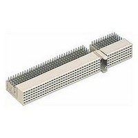
Male connectors, straight Number Contact length [mm] of mating termination Identification contacts side Type Monoblock 47 220 8.2 Type Monoblock 47 / 8.2/ 308 11.2 Type Monoblock 47 220 9.7 Type Monoblock 47 CompactPCI / 8.2/ Positions P1 308 / ...
Page 30
Male connectors, straight Number Contact length [mm] of mating termination Identification contacts side Type Monoblock 47 CompactPCI / 8.2/ I/O 308 / 9.7/ 11.2 Type Monoblock 47 CompactPCI / 9.7/ AB friendly 308 11.2 Positions P4 and P5 Contact dimensions ...
Page 31
... Board drillings Position Row * hole on even contact numbers only needed for lower shielding Part number 17 26 220 1101 17 26 220 2101 17 26 220 1102 17 26 220 2102 17 26 200 1103 17 26 200 2103 17 26 000 4102 17 24 000 4102 17 29 000 4102 ...
Page 32
Notes 11 31 ...
Page 33
Male connectors, straight Number Contact length [mm] of mating termination Identification contacts side Type D 176 8.2 Type D / 8.2/ 220 11.2 Type D / 9.7/ 220 11.2 Contact dimensions [mm Thin print part numbers: performance level ...
Page 34
Male connectors, straight Number Contact length [mm] of mating termination Identification contacts side Type E 200 8.2 Type E / 8.2/ 250 11.2 Type E / 9.7/ 250 11.2 Contact dimensions [mm] Thin print part numbers: performance level 1 Bold ...
Page 35
Male connectors, straight Number Contact length [mm] of mating termination Identification contacts side Type DE 200 8.2 Type DE / 8.2/ 244 11.2 Type DE / 9.7/ 244 11.2 Contact dimensions [mm Thin print part numbers: performance level ...
Page 36
Female connectors, angled Identification Type A Type A with upper shield without shielding Position Row Diameter of drillings: Diameter of plated through holes: Position All holes Row All part numbers: performance level 1 Type A Contact length [mm] No. of ...
Page 37
Female connectors, angled Identification Type B 19 Type B with upper shield 19 Type B 22 Type B with upper shield 22 Type B 25 Type B with upper shield 25 without shielding Position Row Board drillings Diameter of drillings: ...
Page 38
Female connectors, angled Identification Type AB 19 Type AB with upper shield 19 Type AB 22 Type AB with upper shield 22 Type AB 25 Type AB with upper shield 25 without shielding Position Row Board drillings Diameter of drillings: ...
Page 39
Female connectors, angled Identification Type C Type C with upper shield without shielding Position Row All holes Position Row 11 38 All part numbers: performance level 1 Type C Contact length [mm] No. of contacts 55 55 Position Row Board ...
Page 40
Notes 11 39 ...
Page 41
... OBSAI (Open Base Station Architecture Initiative) specifications and provide a reliable and cost effective solution for connecting plug-in units to the backplane. The connector solutions available from the HARTING technology group will offer full compati- bility and intermateability with base station modules. Benefits: Small form factor ...
Page 42
Power Design according : OBSAI System Spezifikation V 1.1 Number of contacts : Contact spacing : 3.00 mm Clearance and creepage distances between contacts : > 2.3 mm Working current : 23 A max. (OBSAI configuration) 20 ...
Page 43
Power Male connectors angled, with press-in termination Identification Connector with same sized contacts Connector with same sized contacts Connector with leading/lagging contacts OBSAI configuration Connector with leading contact Contact dimensions [mm Non-metallized drillings 2) Type XL on ...
Page 44
Power Male connectors angled, with solder (SMC) termination Identification Connector with same sized contacts Connector with leading/lagging contacts OBSAI configuration Contact dimensions [mm] 1) Non-metallized drillings 2) Type XL on request Number Contact length [mm] of termination contacts side Part ...
Page 45
Power Female connector straight, with press-in termination Identification Connector with same sized contacts Connector dimensions [mm] Board drillings 11 44 Number Contact length [mm] of termination contacts side Part number 4 3 004 2201 Position Position All holes ...
Page 46
Coding keys are used to prevent mismating of boards. They can be inserted into the multifunctional area of male and female connectors with special tooling. This can be easily done after the connectors have been pressed in. Coding keys have ...
Page 47
... HARTING's shrouds protect the pins protruding the rear side of the backplane from irregular mating tolerances, thus ensuring a quality connection. To accommodate pcb thickness, from 1 nominal, the shrouds have integrated standoffs of corresponding height. Thus forming a one piece solution that reduces assembling cost significantly. ...
Page 48
Identification Type A shroud 25 positions Dimensions Row Position Shrouds type A Board thickness [mm] 1.6 ± 0.4 2.4 ± 0.4 3.2 ± 0.4 4.0 ± 0.4 Board thickness [mm] 1.6 ± 0.4 2.4 ± 0.4 3.2 ± 0.4 4.0 ...
Page 49
Identification Type B shroud 25 positions 22 positions 19 positions Dimensions Row Position Contact positions 36 42 48) 48 Shrouds type B Board thickness ...
Page 50
Identification Type AB shroud 25 positions 22 positions 19 positions Dimensions Row Position Contact positions x [ 20) Shrouds type AB Board ...
Page 51
Identification Type C shroud 11 positions Dimensions Row Position 11 50 Shrouds type C Board thickness [mm] 1.6 ± 0.4 2.4 ± 0.4 3.2 ± 0.4 4.0 ± 0.4 Board thickness [mm] 1.6 ± 0.4 2.4 ± 0.4 3.2 ± ...
Page 52
... This might be large and heavy boards that bow under their own weight. Also insufficiently aligned or worn out rack systems can be tolerated better with the use of HARTING's guiding system, which also reduces the potential danger of damaging cards when being forced into flexing racks. ...
Page 53
... HARTING customer request form* Should you need a specially loaded connector for your application, please use this request form. Fill out the drawing for the desired connector style and mark each position with the required contact length (A, B, …, S, T). Type A Type B (19 positions) ...
Page 54
... HARTING customer request form Should you need a specially loaded connector for your application, please use this request form. Fill out the drawing for the desired connector style and mark each position with the required contact length (A, B, …, S, T). Type AB (19 positions) ...
Page 55
... HARTING customer request form Should you need a specially loaded connector for your application, please use this request form. Fill out the drawing for the desired connector style and mark each position with the required contact length (A, B, …, S, T). Type D Type E ...
Page 56
Notes 11 55 ...