16-142 Cinch Connectors, 16-142 Datasheet - Page 58
16-142
Manufacturer Part Number
16-142
Description
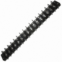
CONN BARRIER BLOCK .563" 16 POS
Manufacturer
Cinch Connectors
Series
142r
Type
Wire to Boardr
Specifications of 16-142
Terminal Block Type
Barrier Block
Number Of Circuits
16
Number Of Positions
32
Pitch
0.563" (14.30mm)
Number Of Rows
2
Current
30A
Voltage
250V
Wire Gauge
10 AWG
Mounting Type
Chassis Mount or Panel Mount
Top Termination
Screws
Bottom Termination
Closed
Barrier Type
2 Wall (Dual)
Features
Flange
Color
Black
Operating Temperature
-55°F ~ 300°F
Material - Insulation
Phenol Formaldehyde (Phenolic)
Material Flammability Rating
UL94 V-1
Connector Type
Barrier Terminal Block
Connector Mounting
Panel
Pitch Spacing
14.29mm
No. Of Contacts
16
Wire Size (awg)
10
Contact Plating
Nickel
Contact Material
Brass
Product
Barrier Terminal Blocks
Number Of Positions / Contacts
16
Current Rating
30 A
Voltage Rating
250 V
Mounting Style
Panel
Termination Style
Screw
Wire Gauge Max (awg)
10
Current, Rating
30 A (Max.)
Length
9.969 in.
Material, Block
Phenolic
Material, Screw
Steel
Plating, Screw
Nickel over Copper Flash
Screw Size
8-32 x 5⁄16
Temperature Range
-55 to +300 °F
Lead Free Status / RoHS Status
Lead free / RoHS Compliant
Lead Free Status / RoHS Status
Lead free / RoHS Compliant, Lead free / RoHS Compliant
Other names
CBB433
Available stocks
Company
Part Number
Manufacturer
Quantity
Price
Company:

Part Number:
16-142
Manufacturer:
TRIDENT
Quantity:
877


CARDCON
Edge Connector
Commercial
Insulation Material: UL 94V-0 rated glass-filled polyester, black
Contact Material: Spring brass
Standard Contact Plating: 10µin. selective gold over nickel, 50µin.
XT, AT Plating: 30µin. selective gold over 50µin. nickel in contact
Shock: Per MIL-STD-202E, Method 213, Condition C
Operating Temperature: -65°C to +105°C
Vibration: Per MIL-STD-202E, Method 204, Condition B
Humidity: Per MIL-STD-202, Method 103, Condition B
Accessories:
Polarizing Key: Two types (order separately):
Card Guide Posts: (order separately)
Individual Contact Insertion and Separation Force:
Call Toll Free: 1 (800) 323-9612
■ AT and XT versions available.
■ Dip solder tails on .200" (5.08mm) row centers double readout.
■ Bifurcated semi-bellows contacts for added contact reliability.
■ Ideal for applications involving vibration or board irregularities.
■ Contact positions: 12, 15, 18, 20, 22, 25, 28, 30, 31, 36, 37, 40, 43, 44, 49,
■ Accepts .062" (1.59mm) thick PC boards.
■ Available less mounting ears, or with .128" (3.25mm) mounting holes or
■ Meets applicable performance criteria of MIL-C-21097.
■ Tube packaging available.
■ UL Recognized - file E170218 (UL1977) E130965 (UL1863).
50, 52, 60, 70, AT, and XT.
4-40 threaded holes.
Insulation Resistance:
Withstanding Voltage:
12oz. maximum with .070" (1.78mm) blade;
1 oz. minimum with .054" (1.37mm) blade
Contact Resistance:
Attach to mounting ears and guide PC board into
connector. See page 2-74 for more information.
™
Current Rating:
area, tin on tails
a) for between-contact polarization and
b) for in-contact polarization.
See page 2-74 for more information.
nickel in contact area, tin on tails
650 VAC RMS (@ sea level)
3 Amps
10 Milliohms maximum
5000 Megohms minimum
.100" (2.54mm) Density
Dip Solder
2-62
Marketed exclusively through distribution.
Related parts for 16-142
Image
Part Number
Description
Manufacturer
Datasheet
Request
R

Part Number:
Description:
CONN BARRIER BLOCK .438" 16 POS
Manufacturer:
Cinch Connectors
Datasheet:

Part Number:
Description:
CONN BARRIER BLOCK .375" 16 POS
Manufacturer:
Cinch Connectors
Datasheet:

Part Number:
Description:
CONN BARRIER BLOCK .375" 16 POS
Manufacturer:
Cinch Connectors
Datasheet:

Part Number:
Description:
TERMINAL BLOCK JUMPER TYPE F
Manufacturer:
Cinch Connectors
Datasheet:

Part Number:
Description:
D-Subminiature Connectors MCHNED PIN 20-24AWG
Manufacturer:
Cinch Connectors
Datasheet:
Part Number:
Description:
Terminal Block,4 Contacts,0.44 Pitch
Manufacturer:
Cinch Connectors
Datasheet:

Part Number:
Description:
Terminal Block,8 Contacts,0.375 Pitch
Manufacturer:
Cinch Connectors
Datasheet: