20-141 Cinch Connectors, 20-141 Datasheet - Page 54
20-141
Manufacturer Part Number
20-141
Description
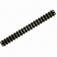
CONN BARRIER BLOCK .438" 20 POS
Manufacturer
Cinch Connectors
Series
141r
Type
Wire to Boardr
Specifications of 20-141
Terminal Block Type
Barrier Block
Number Of Circuits
20
Number Of Positions
40
Pitch
0.438" (11.12mm)
Number Of Rows
2
Current
20A
Voltage
250V
Wire Gauge
14 AWG
Mounting Type
Chassis Mount or Panel Mount
Top Termination
Screws
Bottom Termination
Closed
Barrier Type
2 Wall (Dual)
Features
Flange
Color
Black
Operating Temperature
-55°F ~ 300°F
Material - Insulation
Phenol Formaldehyde (Phenolic)
Material Flammability Rating
UL94 V-1
Connector Type
Barrier Terminal Block
Connector Mounting
Panel
Pitch Spacing
11.11mm
No. Of Contacts
20
Wire Size (awg)
14
Contact Plating
Nickel
Contact Material
Brass
Product
Barrier Terminal Blocks
Number Of Positions / Contacts
20
Current Rating
20 A
Voltage Rating
250 V
Wire Gauge Max (awg)
14
Current, Rating
20 A (Max.)
Length
9.500 in.
Material, Block
Brass
Material, Screw
Steel
Mounting Style
Bottom
Plating, Screw
Nickel over Copper Flash
Screw Size
6-32 x 1⁄4
Temperature Range
-55 to +300 °F
Lead Free Status / RoHS Status
Lead free / RoHS Compliant
Lead Free Status / RoHS Status
Lead free / RoHS Compliant, Lead free / RoHS Compliant
Other names
CBB410


Circular Mini DIN Plugs
Insulation Material: Plug Insulator: UL 94V-0 rated nylon
Contact Material: Plug: Phosphor bronze
Contact Plating:
Shield Material: Steel
Shield Plating: Nickel
Standard Cable Shielded cable with 0.197 inch OD
Composition:
Shock: MIL-STD-202, Method 213, Condition C
Operating Temperature: -40°C to +70°C
Heat Resistance: 196 hrs. at 100°C
Salt Spray: MIL-STD-202, Method 101D, Condition D
Vibration: MIL-STD-202, Method 204, Condition B
Humidity: MIL-STD-202, Method 103, 48 hrs. at 90-95% RH at 40°C
Durability: Withstands 500 mating/unmating cycles
Mating Force: 10 lb. (4.5 kg) maximum
Unmating Force: 1 lb. (0.9 kg) minimum
Contact Retention: 3 lb. minimum
Insulation Resistance:
Call Toll Free: 1 (800) 323-9612
■ Contact positions 3, 4, 5, 6, 7, and 8.
■ Pre-assembled with standard shielded cable lengths; consult factory for other lengths.
■ Molded-in strain relief.
■ Cable and overmold available in standard colors: black or beige.
■ Contacts available with gold over nickel.
■ Shielding system designed to meet FCC requirements for EMI/RFI suppression.
■ UL Recognized - file E170218 (UL1977).
■ CSA Certified - file LR31996-6.
Contact Resistance:
Current Rating:
Voltage Rating:
Option 1: Gold Flash over nickel underplate overall
Option 2: Option 1 plus additional gold in mating area for total
jacket over 28 AWG stranded wire
conductors. Contact factory for custom
cable requirements.
thickness of 30µin.
Plug Overmold: PVC (black or beige)
Cable Jacket: PVC (black or beige)
500 VAC RMS, 707 VDC
1 Amp at 100 VAC
2 Amps at 12 VDC
Contact to contact: 30 milliohms maximum
Shield to shield: 50 milliohms maximum
500 megohms minimum at 500 VDC
100 megohms minimum after humidity
Single-Ended
Cable Assembly
2-58
Marketed exclusively through distribution.
PIN NO
1
2
3
4
5
6
7
8
YELLOW
BROWN
COLOR
GREEN
BLACK
WHITE
BLUE
GRAY
RED
Related parts for 20-141
Image
Part Number
Description
Manufacturer
Datasheet
Request
R

Part Number:
Description:
CONN BARRIER BLOCK .375" 20 POS
Manufacturer:
Cinch Connectors
Datasheet:

Part Number:
Description:
CONN BARRIER BLOCK .375" 20 POS
Manufacturer:
Cinch Connectors
Datasheet:

Part Number:
Description:
Standard Card Edge Connectors CINCH BLK CARD GUIDE
Manufacturer:
Cinch Connectors

Part Number:
Description:
TERMINAL BLOCK JUMPER TYPE F
Manufacturer:
Cinch Connectors
Datasheet:
Part Number:
Description:
D-Subminiature Connectors MCHNED PIN 20-24AWG
Manufacturer:
Cinch Connectors
Datasheet:
Part Number:
Description:
Terminal Block,4 Contacts,0.44 Pitch
Manufacturer:
Cinch Connectors
Datasheet:

Part Number:
Description:
Terminal Block,8 Contacts,0.375 Pitch
Manufacturer:
Cinch Connectors
Datasheet: