7-140 Cinch Connectors, 7-140 Datasheet - Page 220
7-140
Manufacturer Part Number
7-140
Description
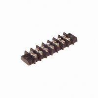
BARRIER BLOCK 7POS .375"
Manufacturer
Cinch Connectors
Series
140r
Type
Wire to Boardr
Specifications of 7-140
Terminal Block Type
Barrier Block
Number Of Circuits
7
Number Of Positions
14
Pitch
0.375" (9.53mm)
Number Of Rows
2
Current
15A
Voltage
250V
Wire Gauge
16 AWG
Mounting Type
Chassis Mount or Panel Mount
Top Termination
Screws
Bottom Termination
Closed
Barrier Type
2 Wall (Dual)
Features
Flange
Color
Black
Operating Temperature
-55°F ~ 300°F
Material - Insulation
Phenol Formaldehyde (Phenolic)
Material Flammability Rating
UL94 V-1
Product
Barrier Terminal Blocks
Number Of Positions / Contacts
7
Current Rating
15 A
Voltage Rating
250 V
Wire Gauge Max (awg)
16
Current, Rating
15 A (Max.)
Length
3.282 in.
Material, Block
Phenolic
Material, Screw
Steel
Mounting Style
Bottom Mount
Plating, Screw
Nickel over Copper Flash
Screw Size
5-40 x 3⁄16
Temperature Range
-55 to +300 °F
Lead Free Status / RoHS Status
Lead free / RoHS Compliant
Lead Free Status / RoHS Status
Lead free / RoHS Compliant, Lead free / RoHS Compliant
Other names
7-140-P
7140-P
CBB107
7140-P
CBB107


5
Dura-Con
High Reliability
MIL-C-83513
NOTE: For additional connector dimensions, see page 5-22.
No. of
Contacts
9 Plug
9 Socket
15 Plug
15 Socket
21 Plug
21 Socket
25 Plug
25 Socket
31 Plug
31 Socket
37 Plug
37 Socket
51 Plug
51 Socket
100 Plug
100 Socket
No. of
Contacts
9 Plug
9 Socket
15 Plug
15 Socket
21 Plug
21 Socket
25 Plug
25 Socket
31 Plug
31 Socket
37 Plug
37 Socket
51 Plug
51 Socket
100 Plug
100 Socket
(/16-/21)
Call Toll Free: 1 (800) 323-9612
1.390
1.390
1.540
1.540
1.690
1.690
1.790
1.790
2.040
2.040
2.340
2.340
1.875
1.875
2.780
2.780
.308
.308
.308
.308
.308
.308
.308
.308
.308
.308
.308
.308
.351
.351
.394
.394
in
in
Max.
Max.
A
G
10.00
10.00
35.31
35.31
39.12
39.12
42.93
42.93
45.47
45.47
51.82
51.82
59.44
59.44
47.63
47.63
70.61
70.61
mm
mm
7.82
7.82
7.82
7.82
7.82
7.82
7.82
7.82
7.82
7.82
7.82
7.82
8.92
8.92
1.150
1.150
1.300
1.300
1.450
1.450
1.550
1.550
1.800
1.800
2.100
2.100
1.600
1.600
2.500
2.500
.190
.200
.190
.200
.190
.200
.190
.200
.190
.200
.190
.200
.190
.200
.190
.200
in
± .007 (0.18)
Recommended Board Layout
in
Max.
B
H
mm
mm
29.21
29.21
33.02
33.02
36.83
36.83
39.37
39.37
45.72
45.72
53.34
53.34
40.64
40.64
63.50
63.50
4.83
5.08
4.83
5.08
4.83
5.08
4.83
5.08
4.83
5.08
4.83
5.08
4.83
5.08
4.83
5.08
.050" (1.27mm) Density
Solder Cup/Wire/PCB
D-Microminiature
1.115
1.115
1.265
1.265
1.215
1.215
1.800
1.800
.565
.565
.715
.715
.865
.865
.965
.965
.096
.096
.096
.096
.096
.096
.096
.096
.096
.096
.096
.096
.096
.096
.125
.125
in
in
± .005 (0.13)
± .005 (0.13)
5-28
C
J
14.35
14.35
18.16
18.16
21.97
21.97
24.51
24.51
28.32
28.32
32.13
32.13
30.86
30.86
45.72
45.72
mm
2.44
2.44
2.44
2.44
2.44
2.44
2.44
2.44
2.44
2.44
2.44
2.44
2.44
2.44
3.18
3.18
mm
.465
.465
.465
.465
.465
.465
.465
.465
.465
.465
.465
.465
.565
.565
.765
.765
.125
.125
.125
.125
.125
.125
.125
.125
.125
.125
.125
.125
.125
.125
.225
.225
in
in
± .015
Max.
K
F
Typ. Hole Dia. = .040" (1.02 mm)
11.81
11.81
11.81
11.81
11.81
11.81
11.81
11.81
11.81
11.81
11.81
11.81
14.35
14.35
19.43
19.43
mm
mm
3.18
3.18
3.18
3.18
3.18
3.18
3.18
3.18
3.18
3.18
3.18
3.18
3.18
3.18
5.72
5.72
Related parts for 7-140
Image
Part Number
Description
Manufacturer
Datasheet
Request
R

Part Number:
Description:
BARRIER BLOCK 7POS .438"
Manufacturer:
Cinch Connectors
Datasheet:

Part Number:
Description:
BARRIER BLOCK 7POS .563"
Manufacturer:
Cinch Connectors
Datasheet:

Part Number:
Description:
CONN BARRIER BLOCK .375" 7 POS
Manufacturer:
Cinch Connectors
Datasheet:
