D-20418-2 Cinch Connectors, D-20418-2 Datasheet - Page 4
D-20418-2
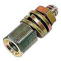
Manufacturer Part Number
D-20418-2
Description
D SUB SCREW LOCK, #4-40 UNC, 70.32MM
Manufacturer
Cinch Connectors
Datasheet
1.D-20418-2.pdf
(282 pages)
Specifications of D-20418-2
Screw Length
7.92mm
Thread Size - Imperial
4-40
Peak Reflow Compatible (260 C)
No
Screw Head Height
4.6mm
Leaded Process Compatible
No
Accessory Type
Female Screw Lock
Rohs Compliant
No
For Use With
D-Subminiature Connectors
Lead Free Status / RoHS Status
Contains lead / RoHS non-compliant


The unique construction of the CIN::APSE contact
provides superior mechanical and electrical performance.
It is constructed of randomly wound molybdenum wire that
is formed into a cyclindrical shape. Standard CIN::APSE
contact diameters are 0.020" and 0.040".
Mechanical
• Small form factor (0.020" diameter by 0.32" min. high)
• Low compression force (approx. 2.5 oz. min. per contact)
• Multiple beam structures
• Several points of contact per button
• Extremely lightweight
• Natural wiping action
Electrical
• Short signal path
• Very low inductance and resistance
• Signal integrity tested in the GHz range
The basic button contact
configuration consists of a single
button installed in our patented
“hourglass” design.
The hourglass cavity retains the
CIN::APSE contact securely.
Typically 0.003" protrudes from the
top and the bottom of the insulator.
CIN::APSE
High-Speed Interconnect Technology
THE BUTTON CONTACT
CIN::APSE APPLIED
®
Step 1:
Using alignment features,
position the CIN::APSE
connector between a LGA chip
package and PCB or two PCBs
that have matching footprints.
1-2
Typical CIN::APSE Applications
• LGA package I/O to PC board (IC packages,
• PC board to PC board (parallel processors,
• Flex circuit to PC board (rigid flex, harnessing)
• Flex circuit to ceramic (chip to harness)
multi-chip modules)
enhancement/mezzanine cards)
Step 2:
Add Z-Axis compression
and secure.
Call Toll Free: 1 (800) 323-9612
Related parts for D-20418-2
Image
Part Number
Description
Manufacturer
Datasheet
Request
R

Part Number:
Description:
HOUSING, SIZE 1, BOTTOM ENTRY
Manufacturer:
TE Connectivity
Datasheet:

Part Number:
Description:
HOUSING, SIZE 5, BOTTOM ENTRY
Manufacturer:
TE Connectivity
Datasheet:

Part Number:
Description:
HOUSING, SIZE 3, SIDE ENTRY, M25
Manufacturer:
TE Connectivity
Datasheet:

Part Number:
Description:
D SUB LATCHING BLOCK, #4-40
Manufacturer:
TE Connectivity
Datasheet:

Part Number:
Description:
CONN LATCH SPRING DB9-37 2/BAG
Manufacturer:
Tyco Electronics
Datasheet: