95B Cinch Connectors, 95B Datasheet - Page 58
95B
Manufacturer Part Number
95B
Description
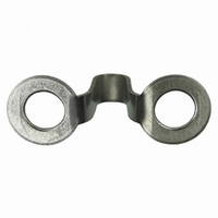
TERMINAL BLOCK JUMPER TYPE F
Manufacturer
Cinch Connectors
Type
Barrier Blockr
Series
142r
Specifications of 95B
Number Of Positions
2
Style
Over Barrier, Ring Tongue
Product
Barrier Terminal Blocks
Number Of Positions / Contacts
17
Color
Black
Accessory Type
Jumper
No. Of Positions
2
Body Material
Brass
Leaded Process Compatible
No
No. Of Contacts
2
Rohs Compliant
Yes
Lead Free Status / RoHS Status
Lead free / RoHS Compliant
For Use With/related Products
142 Series
Lead Free Status / Rohs Status
Lead free / RoHS Compliant
For Use With
Barrier Block Series 142
Lead Free Status / RoHS Status
Lead free / RoHS Compliant, Lead free / RoHS Compliant
Other names
CBB318
Available stocks
Company
Part Number
Manufacturer
Quantity
Price

Part Number:
95B
Manufacturer:
PHILIPS/飞利浦
Quantity:
20 000
Part Number:
95BWHCD50M00
Manufacturer:
FC
Quantity:
20 000


CARDCON
Edge Connector
Commercial
Insulation Material: UL 94V-0 rated glass-filled polyester, black
Contact Material: Spring brass
Standard Contact Plating: 10µin. selective gold over nickel, 50µin.
XT, AT Plating: 30µin. selective gold over 50µin. nickel in contact
Shock: Per MIL-STD-202E, Method 213, Condition C
Operating Temperature: -65°C to +105°C
Vibration: Per MIL-STD-202E, Method 204, Condition B
Humidity: Per MIL-STD-202, Method 103, Condition B
Accessories:
Polarizing Key: Two types (order separately):
Card Guide Posts: (order separately)
Individual Contact Insertion and Separation Force:
Call Toll Free: 1 (800) 323-9612
■ AT and XT versions available.
■ Dip solder tails on .200" (5.08mm) row centers double readout.
■ Bifurcated semi-bellows contacts for added contact reliability.
■ Ideal for applications involving vibration or board irregularities.
■ Contact positions: 12, 15, 18, 20, 22, 25, 28, 30, 31, 36, 37, 40, 43, 44, 49,
■ Accepts .062" (1.59mm) thick PC boards.
■ Available less mounting ears, or with .128" (3.25mm) mounting holes or
■ Meets applicable performance criteria of MIL-C-21097.
■ Tube packaging available.
■ UL Recognized - file E170218 (UL1977) E130965 (UL1863).
50, 52, 60, 70, AT, and XT.
4-40 threaded holes.
Insulation Resistance:
Withstanding Voltage:
12oz. maximum with .070" (1.78mm) blade;
1 oz. minimum with .054" (1.37mm) blade
Contact Resistance:
Attach to mounting ears and guide PC board into
connector. See page 2-74 for more information.
™
Current Rating:
area, tin on tails
a) for between-contact polarization and
b) for in-contact polarization.
See page 2-74 for more information.
nickel in contact area, tin on tails
650 VAC RMS (@ sea level)
3 Amps
10 Milliohms maximum
5000 Megohms minimum
.100" (2.54mm) Density
Dip Solder
2-62
Marketed exclusively through distribution.
Related parts for 95B
Image
Part Number
Description
Manufacturer
Datasheet
Request
R

Part Number:
Description:
Standard Card Edge Connectors CINCH BLK CARD GUIDE
Manufacturer:
Cinch Connectors
Part Number:
Description:
D-Subminiature Connectors MCHNED PIN 20-24AWG
Manufacturer:
Cinch Connectors
Datasheet:
Part Number:
Description:
Terminal Block,4 Contacts,0.44 Pitch
Manufacturer:
Cinch Connectors
Datasheet:

Part Number:
Description:
Terminal Block,8 Contacts,0.375 Pitch
Manufacturer:
Cinch Connectors
Datasheet: