12-404-PB30-02 Altium, 12-404-PB30-02 Datasheet
12-404-PB30-02
Manufacturer Part Number
12-404-PB30-02
Description
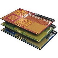
PB30 Prototyping Peripheral Board (20PK)
Manufacturer
Altium
Datasheet
1.12-404-PB30-02.pdf
(1 pages)
Specifications of 12-404-PB30-02
Kit Contents
Prototyping Peripheral Board
Tool / Board Applications
General Purpose FPGA, CPLD
Supported Devices
NanoBoard NB2 Or 3000-series
Altium
Highlights
Specifications
Availability
Resource materials
Altium provides extensive online resources designed to get you up and running as quickly as possible.
For information on all available NanoBoard configurations,
visit the Altium website at www.altium.com/nanoboard
•
•
•
•
•
•
•
•
•
•
•
•
Provides a rapid prototyping space to quickly test out additional hardware resources –
made available for use by the User FPGA device on a NanoBoard NB2 or NanoBoard 3000.
Plugs directly into the peripheral board connector on-board a NanoBoard 3000, or peripheral board
connectors A or C of a NanoBoard NB2.
Pre-defined land patterns for easy location of surface mount devices (with 0.5mm, 0.65mm, 0.8mm,
and 1.27mm pitches). Each SMD pad is connected to a 0.5mm hole to allow simple connections using
prototyping wire.
General purpose areas offering 0.1” (thru-hole) and 0.05” pitches.
Board identification achieved through provision of a 1-Wire compatible slave memory device (DS2502).
Provides easy access to generic IO and common services.
Single on-board connector follows standard Altium peripheral board pinout providing easy access to
the following generic IO and common services:
Standard, double-sized peripheral board.
3 standard board colors – red, green and blue.
High-quality gold PCB finish.
Available in packs of 3 or 20 boards (all colors included in each pack).
Full technical information on the Prototyping peripheral board – www.altium.com/wiki/pb30
- 50 x general purpose IO (IO01 – IO50).
- Hard and Soft JTAG signals – allowing for inclusion of a JTAG-equipped physical device such as an
- Audio signals – Line In (L+R), Line Out (L+R) and Mic In.
- I2C interface (SDA, SCL) – allowing use of resources possessing an I2C-compatible interface.
- SPI Bus interface, with two dedicated chip select lines – allowing for up to two SPI-based resources.
- 1-Wire Bus interface signal (1W) – allowing for use of one or more slave 1-Wire compatible devices.
- Four pins made available to receive gated clock signals from the NanoBoard’s Host (NanoTalk)
- Power signals – +5V, +3V3, +2V5, +1V8, +1V2, and GND.
additional FPGA resource.
Controller (3 clock signals and 1 enable signal).
Prototyping Peripheral Board
Related parts for 12-404-PB30-02
Image
Part Number
Description
Manufacturer
Datasheet
Request
R


Part Number:
Description:
USB / IRDA / ETHERNET PB03 PERIPHERAL BOARD
Manufacturer:
Altium

Part Number:
Description:
PB30 Prototyping Peripheral Board (3PK)
Manufacturer:
Altium
Datasheet:

Part Number:
Description:
KIT NANOBOARD AND CYCLONEII DC
Manufacturer:
Altium


Part Number:
Description:
KIT NANOBOARD AND LATTICEECP DC
Manufacturer:
Altium


Part Number:
Description:
NanoBoard 3000 Modular Enclosure
Manufacturer:
Altium
Datasheet:


Part Number:
Description:
Standard LED - SMD Orange, 605nm 50mcd, 20mA
Manufacturer:
Everlight Electronics CO., LTD

Part Number:
Description:
Standard LED - SMD Green Water Clear Right Angle
Manufacturer:
Everlight Electronics CO., LTD
Datasheet:

Part Number:
Description:
Standard LED - SMD Hyper Red Right Angle
Manufacturer:
Everlight Electronics CO., LTD
Datasheet:

Part Number:
Description:
Standard LED - SMD RGB Water Clear
Manufacturer:
Everlight Electronics CO., LTD
Datasheet:
Part Number:
Description:
Manufacturer:
Everlight Electronics CO., LTD
Datasheet: