MC-MEGA MULTICOMP, MC-MEGA Datasheet - Page 3
MC-MEGA
Manufacturer Part Number
MC-MEGA
Description
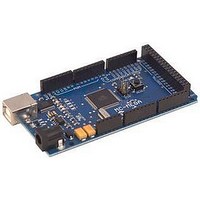
Arduino MEGA Based Board W/ ATMEGA1280
Manufacturer
MULTICOMP
Datasheet
1.MC-MEGA.pdf
(4 pages)
Specifications of MC-MEGA
Silicon Manufacturer
Atmel
Core Architecture
AVR
Features
16MHz Crystal Oscillator, ICSP Header
Kit Contents
Development Board Only
Silicon Family Name
Atmega
Lead Free Status / RoHS Status
Lead free / RoHS Compliant


Programming
The MC-MEGA can be programmed with the Arduino™ software (download). For details, see the reference and tutorials.
The ATmega1280 on the MC-MEGA comes pre-burned with a bootloader that allows you to upload new code to it without the use of
an external hardware programmer. It communicates using the original STK500 protocol (reference, C header files).
You can also bypass the bootloader and program the microcontroller through the ICSP (In-Circuit Serial Programming) header; see
these instructions for details.
Automatic (Software) Reset
Rather than requiring a physical press of the reset button before an upload, the MC-MEGA is designed in a way that allows it to be
reset by software running on a connected computer. One of the hardware flow control lines (DTR) of the FT232RL is connected to
the reset line of the ATmega1280 via a 100 nanofarad capacitor. When this line is asserted (taken low), the reset line drops long
enough to reset the chip. The Arduino™ software uses this capability to allow you to upload code by simply pressing the upload
button in the Arduino environment. This means that the bootloader can have a shorter timeout, as the lowering of DTR can be well-
coordinated with the start of the upload.
This setup has other implications. When the Mega is connected to either a computer running Mac OS X or Linux, it resets each time
a connection is made to it from software (via USB). For the following half-second or so, the bootloader is running on the Mega.
While it is programmed to ignore malformed data (i.e. anything besides an upload of new code), it will intercept the first few bytes of
data sent to the board after a connection is opened. If a sketch running on the board receives one-time configuration or other data
when it first starts, make sure that the software with which it communicates waits a second after opening the connection and before
sending this data.
The Mega contains a trace that can be cut to disable the auto-reset. The pads on either side of the trace can be soldered together
to re-enable it. It's labelled "RESET-EN". You may also be able to disable the auto-reset by connecting a 110 ohm resistor from 5V
to the reset line; see this forum thread for details.
USB Overcurrent Protection
The MC-MEGA has a resettable polyfuse that protects your computer's USB ports from shorts and overcurrent. Although most
computers provide their own internal protection, the fuse provides an extra layer of protection. If more than 500 mA is applied to the
USB port, the fuse will automatically break the connection until the short or overload is removed.
Physical Characteristics and Shield Compatibility
The maximum length and width of the Mega PCB are 4 and 2.1 inches respectively, with the USB connector and power jack
extending beyond the former dimension. Three screw holes allow the board to be attached to a surface or case. Note that the
distance between digital pins 7 and 8 is 160 mil (0.16 inches), not an even multiple of the 100 mil spacing of the other pins.
Schematic & Reference Design
EAGLE files: arduino-mega-reference-design.zip
Schematic: arduino-mega-schematic.pdf
MC-MEGA
Arduino™ Compatible Development Board
http://www.farnell.com
http://www.newark.com
http://www.cpc.co.uk
Page <3>
28/05/10 V1.1
Related parts for MC-MEGA
Image
Part Number
Description
Manufacturer
Datasheet
Request
R

Part Number:
Description:
Arduino NANO Based Board W/ ATMEGA328
Manufacturer:
MULTICOMP
Datasheet:

Part Number:
Description:
Arduino Duemilanove Based Board W/ ATMEGA328
Manufacturer:
MULTICOMP
Datasheet:

Part Number:
Description:
MC-10105F1-821-FNA-A
Manufacturer:
Renesas Electronics Corporation.

Part Number:
Description:
CAP, PROTECTIVE, BLACK
Manufacturer:
MC (MULTI CONTACT)
Datasheet:

Part Number:
Description:
Semiconductor Selection Guide
Manufacturer:
NEC
Datasheet:
Part Number:
Description:
Manufacturer:
Renesas Electronics Corporation.
Datasheet:
Part Number:
Description:
MCP (MULTI-CHIP PACKAGE) FLASH MEMORY AND SRAM 64M-BIT PAGE MODE FLASH MEMORY AND 8M-BIT SRAM
Manufacturer:
NEC

Part Number:
Description:
16M-WORD BY 64-BIT SYNCHRONOUS DYNAMIC RAM MODULE SO DIMM
Manufacturer:
NEC
Datasheet:
Part Number:
Description:
16m-word By 72-bit Synchronous Dynamic Ram Module Unbuffered Type
Manufacturer:
Renesas Electronics Corporation.
Datasheet:

Part Number:
Description:
32m-word By 72-bit Synchronous Dynamic Ram Module Unbuffered Type
Manufacturer:
Elpida Memory, Inc.
Datasheet: