FPT-1+FPT-EPF10K10TC144 LEAP ELECTRONIC, FPT-1+FPT-EPF10K10TC144 Datasheet
FPT-1+FPT-EPF10K10TC144
Manufacturer Part Number
FPT-1+FPT-EPF10K10TC144
Description
MODULE, FPT-1 WITH ALTERA CHIP
Manufacturer
LEAP ELECTRONIC
Datasheet
1.FPT-1FPT-EPF10K10TC144.pdf
(1 pages)
Specifications of FPT-1+FPT-EPF10K10TC144
Development Tool Type
Demonstration Kit
Kit Features
Programmed Finished File To EPROM, CPLD / FPGA Software And Hardware, Graphic & VHDL, ABEL, AHDL
Mcu Supported Families
ALTERA EPF10K10TC144,
Silicon Manufacturer
Altera
Kit Contents
Board
Features
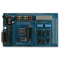
8x2 LED Shown Output, 8x2 Logical Input Toggle, Four Pulse Keystrokes Producer
Brief Introduction
engineer designed circuits need a universal
bread board and a great quantity's logical
devices. Only soldering each devices can
make people feel so frustrated, not to say
amended it when you made a mistake. Now
an electronic engineer can finished designed
circuits easily by using CPLD / FPGA only
amended on software and operated it via soft-
ware. It is like made your own PC circuit
device on the test table. It is not only learn
new chip's techniques but it can also reduce
PC board 's ALTERA then create a compact
electronic product.
port beginners needing, designed two big
brands ALTERA and XILINX's CPLD/FPGA
platform for user to study. Avoiding troubles
of both soldering QFP chips and experimental
layout. We had been approved by both IC ven-
dors to use their development software. It will
eliminate the hinder and stride enter domain
CPLD/FPGA fields
FEATURES
FPT-1
!
!
!
!
!
U s e C P L D / F P G A s o f t w a r e a n d
hardware to learn new logical IC design,
i n o r d e r t o r e p l a c e T T L / C M O S
complicated hardware design.
Use Graphic and VHDL
AHDL to develop circuits
Use Print Port Download directly
under original manufacturer develop-
ment system
Programmed finished file to EPROM
(FLASH) and operated it independ-
ently
Use WIN95/98/2000/NT operation
system.
In the past, A professional electronic
LEAP ELECTRONIC CO., LTD. sup-
CPLD/FPGA Logical Circuit Design Experimental Board
ABEL
CHARACTERISTIC
FPT-1 Experimental Board
Hardware Specifications
!
!
!
!
1. Support Devices
2. 8x2 LED shown output.
3. 8x2 Logical input toggle
4. Four pulse keystrokes producer two
5. Six digits and seven nodes monitor
6. Own Red main power guiding lights
7. Within 10MHz oscillator
8. Own main power switch to exchange
9. 25pin D Type Connector Printer Port
10.Use DC 9V Adaptor or Extend Power
11.Support ALTERA MAX +Plus II
12.Not use expanded area I/O Pin
Module design
User can select the different chip
board module to be purchases.
Expensive chip can re-use
Without soldering QFP package and
saving much time.
:DC 5V
positive pulses two negative pulses)
(1)ALTERA EPF10K10TC144
(2)XILINX XCS10TQ144
Adaptor with Extend Power Pin
Download FPGA
Pin provided for user. Specification
Baseline and XILINX Foundation's
development system.
provided user definition use
FPT-EPF10K10TC144
FPT-XCS10TQ144
TQFP144pin
TQFP144pin
.
Test Content
Thematic Application Test
Application program range
Optional Accessories:
Please indicate ALTERA or XILINX series
Chip board module when you Order them.
!
!
!
!
!
!
!
!
!
Combined logic design, simulation and
test:
1. Basic logic
2. Deducter
3. Decoder
4. Combined logic
5. Comparator
6. Multiplexer
7. Adder
8. Compiler
9. Demultiplexer
Sequential logic circuit design simula-
tion and test:
1. Flep-flop device
2. Shift register
3. Shift counter register
4. Synchronized counter
5. Non-Synchronized counter
Digital clock
Counter
Electronic alarm clock
Traffic light control
Electronic dice
VHDL/AHDL design
1. Fundamental logic
2. Digital circuit design
3. Digital System Design
4. Microprocessor Principle
5. CPLD/FPGA Chip Design
Random design of expanded I/O Pin
Related parts for FPT-1+FPT-EPF10K10TC144
Image
Part Number
Description
Manufacturer
Datasheet
Request
R

Part Number:
Description:
FPT ALUM CARPET PLATE 1/2IN PLUG
Manufacturer:
THOMAS & BETTS

Part Number:
Description:
EMULATOR, 4M ROM USB, W/O ADAPTOR
Manufacturer:
LEAP ELECTRONIC
Datasheet:

Part Number:
Description:
DESIGNER BOARD, CPLD/FPGA, LOGIC CCT
Manufacturer:
LEAP ELECTRONIC
Datasheet:

Part Number:
Description:
EPROM ERASER, W/O ADAPTOR
Manufacturer:
LEAP ELECTRONIC
Datasheet:

Part Number:
Description:
PROGRAMMER, STANDALONE/PC MODE, W/O PSU
Manufacturer:
LEAP ELECTRONIC
Datasheet:

Part Number:
Description:
USB Flash Writer Programmer
Manufacturer:
LEAP ELECTRONIC
Datasheet:

Part Number:
Description:
PROGRAMMER, USB, MCS-51, W/O PSU
Manufacturer:
LEAP ELECTRONIC
Datasheet:
Part Number:
Description:
EPROM ERASER
Manufacturer:
LEAP ELECTRONIC
Datasheet:
Part Number:
Description:
ADAPTOR, PLCC SOCKET-PLCC PKG, 20PIN
Manufacturer:
LEAP ELECTRONIC
Datasheet:
Part Number:
Description:
ADAPTOR, SOP SOCKET-SOP PKG, 44PIN
Manufacturer:
LEAP ELECTRONIC
Datasheet:

Part Number:
Description:
ADAPTOR, TSOP SOCKET-TSOP PKG, 48PIN
Manufacturer:
LEAP ELECTRONIC
Datasheet:

Part Number:
Description:
ADAPTOR, TSOP SOCKET, SPRING, 48PIN
Manufacturer:
LEAP ELECTRONIC
Datasheet:
Part Number:
Description:
ADAPTOR, SOP SOCKET-SOP PKG, 32PIN
Manufacturer:
LEAP ELECTRONIC
Datasheet:
Part Number:
Description:
01M8114
Manufacturer:
LEAP ELECTRONIC
Datasheet: