HFBR-0572 Avago Technologies US Inc., HFBR-0572 Datasheet

Fiber Optics, Evaluation Kit

HFBR-0572

Manufacturer Part Number
HFBR-0572
Description
Fiber Optics, Evaluation Kit
Manufacturer
Avago Technologies US Inc.
Datasheet

Specifications of HFBR-0572

Silicon Core Number
HFBR-5921L, HFBR-5923L
Kit Contents
Evaluation PC Board, Associated Technical Literature
Features
Applicable For Evaluating 2x5 Or 2x6 Pin Small Form Factor Transceivers
Main Purpose
Interface, Fiber Optics
Embedded
No
Utilized Ic / Part
HFBR-5921L, HFBR-5923L
Primary Attributes
SFP PTH Multimode Fibre Channel Applications
Secondary Attributes
Small Form Factor Pluggable (SFP)
Description/function
Fiber Optic Kit
Lead Free Status / RoHS Status
Lead free / RoHS Compliant
For Use With/related Products
HFBR-5921L, HFBR-5923L
Lead Free Status / RoHS Status
Lead free / RoHS Compliant, Contains lead / RoHS non-compliant
Through Hole Transceivers
Application Note 1245
SFF Evaluation Board
The purpose of this Small Form Factor (SFF) through
hole evaluation board is to provide the designer with
a convenient means to evaluate the performance of
10- or 12-pin SFF fiber optic transceivers such as the
HFBR-5921L and HFBR-5923L, as well as future SFF MSA
compatible product offerings. This document describes
the details of the evaluation printed circuit board (PCB)
and the test equipment and methods for evaluating SFF
modules. The detailed operation of the SFF modules
and test equipment used with this evaluation PCB are
not described in this document, but can be found by
obtaining the appropriate documents from the refer-
ence section.
Document Outline
I.
II.
III. Electro-Optical Test Configuration(s)
IV. Evaluation PCB Schematic and Bill of Materials
V.
Equipment List
Evaluation PCB Description
Reference
I. Equipment List
Included:
1.
2.
Not Included:
1.
2.
3.
4.
5.
6.
7.
II. Evaluation PCB Description
Top and bottom views of the evaluation PCB are shown
in Figure 1. A description of all of the Input/Output (I/O)
interfaces on the PCB is shown in Table 1, all of which
are found, on the topside of the PCB. The evaluation
PCB is a 4-layer design compatible with high-speed
signal I/O rates up to 2.125 GBd.
Evaluation PCB
SFF 2 x 6 transceiver module(s)
3.3 V DC power supply
Fiber optic cables
– LC to SC (1 M and 50/125 µm or 62.5/125 µm)
– LC to LC Loopback (<1 M and 50/125 µm or 62.5/125
86100A Agilent Digital Communications Analyzer
(DCA)
86103A Agilent Optical/Electrical DCA Plug-In Module
Option H43 or H21 (2.125 FC)
86130A Agilent Bit Alyzer 3 Gb/s Bit Error Rate Tester
(BERT)
– Pattern generator, error detector/analyzer
Fiber Optic Attenuator (optional)
PC (optional)
µm or 9/125 µm)

Related parts for HFBR-0572

HFBR-0572 Summary of contents

Page 1

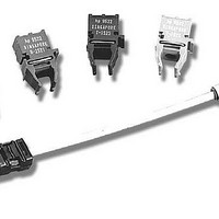
... SFF fiber optic transceivers such as the HFBR-5921L and HFBR-5923L, as well as future SFF MSA compatible product offerings. This document describes the details of the evaluation printed circuit board (PCB) and the test equipment and methods for evaluating SFF modules ...

Page 2

Figure 1. SFF Evaluation Board Top and Bottom View 2 ...

Page 3

Table 1 - I/O Description Reference Designator Name VccT J7 VeeT J8 VccR J9 VeeR J10 TX Fault J11 1X/2X Rate J15 TX VCC JUMP ...

Page 4

III. Electro-Optical Test Configuration(s) The two basic test configurations for evaluating the 10- or 12-pin SFFs are shown in Figure 2 (transmitter) and Figure 3 (receiver or loopback). These test configura- tions use one evaluation board and the test instruments ...

Page 5

IV. Evaluation Board Schematic and Bill of Materials The SFF evaluation PCB electrical schematic is shown in Figure 6 at the end of this document. The user may notice connections on the board which are not repre- sented on this ...

Page 6

Table 2 - SFF Evaluation Board Bill of Materials. Component Type PCB SFF Evaluation Board U1 Surface Mount Socket (20 pin) Case jacks Q1 Transistor Device jacks Nose jacks R4 Resistor R3,R5 Resistor C5,C7,C8,C10 Capacitor C6,C9,C12,C13 Capacitor L1,L2 Inductor SW1 ...

Page 7

7 ...

Page 8

... VI. References 1. HFBR-59xx Product Data Sheets 2. Avago Technologies’ Application Notes (AN) – http://www.avagotech.com 3. Small Form Factor (SFF) Transceiver Multi-Source Agree- ment. Revised July 5, 2000. Please contact your local Avago Technologies field sales engineer for a copy of this document. 4. Small Form Factor Pluggable (SFP) Transceiver Multi- Source Agreement ...

Related keywords