HFBR-0560 Avago Technologies US Inc., HFBR-0560 Datasheet - Page 7
HFBR-0560
Manufacturer Part Number
HFBR-0560
Description
Fiber Optics, Evaluation Kit
Manufacturer
Avago Technologies US Inc.
Datasheet
1.HFBR-0559.pdf
(16 pages)
Specifications of HFBR-0560
Silicon Manufacturer
Avago
Silicon Core Number
HFBR-5903/5903E/5903A
Kit Application Type
Communication & Networking
Application Sub Type
Ethernet Transceiver
Main Purpose
Interface, Ethernet
Embedded
No
Utilized Ic / Part
HFBR-5903, FDDL, Fast Ethernet Transceivers
Primary Attributes
MT-RJ 125Mb/s, Multimode and Singlemode Applications
Secondary Attributes
MT-RJ Fiber Connector Interface
Description/function
Fiber Optic Kit
Lead Free Status / RoHS Status
Lead free / RoHS Compliant
For Use With/related Products
HFCT-5903E
Lead Free Status / RoHS Status
Lead free / RoHS Compliant, Contains lead / RoHS non-compliant


The Avago Technologies 1300 nm receivers will tolerate
the worst case input optical jitter allowed in Sections
8.2 Active Input Interface of the FDDI PMD and LCF-
PMD standards without violating the worst case output
electrical jitter allowed in Table E1 of Annex E.
The jitter specifications stated in the following 1300
nm transceiver specification tables are derived from
the values in Table E1 of Annex E. They represent the
worst case jitter contribution that the transceivers are
allowed to make to the overall system jitter without
violating the Annex E allocation example. In practice
the typical contribution of the Avago Technologies
transceivers is well below these maximum allowed
amounts.
Recommended Handling Precautions
Avago Technologies recommends that normal static
precautions be taken in the handling and assembly of
these transceivers to prevent damage which may be
induced
Figure 8. Alternative Termination Circuits
7
TX
RX
Note: C1 = C2 = C3 = 10 nF or 100 nF
by
10
1
9
2
electrostatic
8
3
7
4
6
5
discharge
130 Ω
82 Ω
TRANSCEIVER INPUTS
C2
C1
1 µH
1 µH
TERMINATE AT
V CC (+3.3 V)
130 Ω
82 Ω
Z = 50 Ω
Z = 50 Ω
Z = 50 Ω
V CC (+3.3 V)
(ESD).
C3
10 nF
10 µF
The HFBR-5900 series of transceivers meet MIL-STD-
883C Method 3015.4 Class 2 products.
Care should be used to avoid shorting the receiver data
or signal detect outputs directly to ground without
proper current limiting impedance.
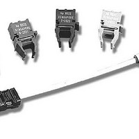
Solder and Wash Process Compatibility
The transceivers are delivered with protective process
plugs inserted into the MT-RJ connector receptacle. This
process plug protects the optical subassemblies during
wave solder and aqueous wash processing and acts as
a dust cover during shipping.
These transceivers are compatible with either industry
standard wave or hand solder processes.
Shipping Container
The transceiver is packaged in a shipping container
designed to protect it from mechanical and ESD
damage during shipment or storage.
TERMINATE AT DEVICE INPUTS
V CC (+3.3 V)
130 Ω
82 Ω
10 nF
10 nF
130 Ω
Z = 50 Ω
Z = 50 Ω
82 Ω
V CC (+3.3V)
130 Ω
82 Ω
TD-
TD+
RD+
RD-
SD
PHY DEVICE
V CC (+3.3 V)
LVPECL
V CC (+3.3 V)
LVPECL
Related parts for HFBR-0560
Image
Part Number
Description
Manufacturer
Datasheet
Request
R

Part Number:
Description:
Fiber Optic Transmitters, Receivers, Transceivers 1300nm 155MBd 16-pin DIP ST Rx
Manufacturer:
Avago Technologies US Inc.

Part Number:
Description:
FIBER OPTIC TX 125 MBD 650N
Manufacturer:
Avago Technologies US Inc.
Datasheet:

Part Number:
Description:
Fiber Optic Evaluation Kit
Manufacturer:
Avago Technologies US Inc.
Datasheet:

Part Number:
Description:
RECEIVER FIBER OPTIC ST 266MBD
Manufacturer:
Avago Technologies US Inc.
Datasheet:

Part Number:
Description:
RCVR OPT HI SPEED VERS LINK HORZ
Manufacturer:
Avago Technologies US Inc.
Datasheet:

Part Number:
Description:
RCVR OPT HI SPEED VERS LINK VERT
Manufacturer:
Avago Technologies US Inc.
Datasheet:

Part Number:
Description:
TXRX OPTICAL 850NM VCSEL MT-RJ
Manufacturer:
Avago Technologies US Inc.
Datasheet:

Part Number:
Description:
TXRX MM SFP LC CONN BAIL DELATCH
Manufacturer:
Avago Technologies US Inc.
Datasheet:

Part Number:
Description:
TXRX MMF SFP GBE/FC BAIL DELATCH
Manufacturer:
Avago Technologies US Inc.
Datasheet:

Part Number:
Description:
XMITTER FIBER OPTIC 266MBD ST
Manufacturer:
Avago Technologies US Inc.
Datasheet:

Part Number:
Description:
OPTOCOUPLER GATE DRV 2A 16-SOIC
Manufacturer:
Avago Technologies US Inc.
Datasheet:
Part Number:
Description:
OPTOCOUPLER 2CH 2.5A 16-SOIC
Manufacturer:
Avago Technologies US Inc.
Datasheet:

Part Number:
Description:
OPTOCOUPLER GATE DRV 0.4A 16SOIC
Manufacturer:
Avago Technologies US Inc.
Datasheet:

Part Number:
Description:
OPTOCOUPLER 2.0A 250KHZ 8-DIP
Manufacturer:
Avago Technologies US Inc.
Datasheet:

Part Number:
Description:
OPTOCOUPLER 2.0A 250KHZ GW 8-SMD
Manufacturer:
Avago Technologies US Inc.
Datasheet: