DB63R APEX PRECISION POWER, DB63R Datasheet - Page 3
DB63R
Manufacturer Part Number
DB63R
Description
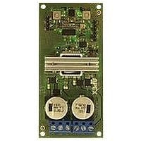
DC Brush Motor Driver Demo Board
Manufacturer
APEX PRECISION POWER
Datasheet
1.DB63R.pdf
(6 pages)
Specifications of DB63R
Silicon Manufacturer
Cirrus Logic
Silicon Core Number
SA57
Kit Application Type
Power Management - Motor Control
Application Sub Type
DC Brushed Motor
Kit Contents
Board Docs


DB63R
P r o d u c t I n n o v a t i o n F r o m
Figure 3 – Schematic
ENHANCINg & BYPASSINg THE DB63R CONTROL CIRCUIT:
Connector J5 allows the user to bypass many of the manual control features of the DB63R. A signal generator can
control the duty cycle with a 2.5 to 7.5V signal, overriding the control potentiometer. A rising 5V edge on pin 3 or 4 of
connector J5 will toggle the Direction or Enable latches, respectively. By jumping resistors R24 & R25, the latches
are bypassed completely and the logic signals on pins 3 & 4 will directly control the direction and enable functions of
the DB63R. With these resistors jumped, the direction and enable LEDs will not represent the states of the DB63R
and the pushbuttons will have no effect on the operation. The Temperature disable feature of the DB63R will also
not function, although the LED will continue to provide over-temperature status.
Connector J4 is connected directly to the PWM input pins of the SA57. This connector may be used to monitor the
signals or to bypass the control IC on the DB63R. The enable function is not controlled via these pins, although
pulling all four input pins low provides the same effect. The Enable pushbutton and the connection via J5 are also
effective as previously described. The circuit shown in figure 3 in the dashed box is a simple circuit that allows the
user to monitor and control the enable or direction status remotely. Either feature can be toggled on the falling edge
of the signal at the node labeled TOGGLE.
LAYOUT CONSIDERATIONS
A simple two layer construction is sufficient because of the convenient pinout of the SA57 PowerQuad package.
Input signals are routed into one side of the package and high power output signals are routed from the other side
in 2 ounce copper. This eliminates the need to route control signals near motor connections where noise may cor-
rupt the signals. Filling top and bottom layers with copper reduces inductive coupling from the high current outputs.
1nF capacitors with excellent high frequency characteristics bypass the Vs motor supplies on each phase. Two
150μF electrolytic capacitors provide a local, low inductance source to accommodate surge currents up to 17A.
DB63RU
3
Related parts for DB63R
Image
Part Number
Description
Manufacturer
Datasheet
Request
R

Part Number:
Description:
DEMO BOARD FOR SA57-IHZ
Manufacturer:
Cirrus Logic Inc
Datasheet:

Part Number:
Description:
IC, OP-AMP, 90KHZ, 30V/µs, TO-3-8
Manufacturer:
APEX PRECISION POWER
Datasheet:
Part Number:
Description:
IC, OP-AMP, 60KHZ, 30V/µs, TO-3-8
Manufacturer:
APEX PRECISION POWER
Datasheet:
Part Number:
Description:
IC, OP-AMP, 6KHZ, 30V/µs, TO-3-8
Manufacturer:
APEX PRECISION POWER
Datasheet:
Part Number:
Description:
IC, OP-AMP, 75MHZ, 180V/µs, TO-3-8
Manufacturer:
APEX PRECISION POWER
Datasheet:
Part Number:
Description:
IC, POWER OP-AMP, SINGLE, 150MHZ, TO-3-8
Manufacturer:
APEX PRECISION POWER
Datasheet:
Part Number:
Description:
IC, POWER OP-AMP, SINGLE, 150MHZ, TO-3-8
Manufacturer:
APEX PRECISION POWER
Datasheet:

Part Number:
Description:
HIGH POWER AMP MODULE 65V/USSLEW
Manufacturer:
Cirrus Logic Inc
Datasheet:

Part Number:
Description:
IC, OP-AMP, 180MHZ, 3000V/µs, SIP-12
Manufacturer:
APEX PRECISION POWER
Part Number:
Description:
Evaluation Kit, MP108FD,MP111FD
Manufacturer:
APEX PRECISION POWER
Datasheet: