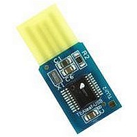
TEALEAF-USB HEXWAX, TEALEAF-USB Datasheet - Page 2

TEALEAF-USB
Manufacturer Part Number
TEALEAF-USB
Description
TEAleaf-USB Authentication System
Manufacturer
HEXWAX
Datasheet
1.TEALEAF-USB.pdf
(8 pages)
Specifications of TEALEAF-USB
Silicon Manufacturer
FirmWare Factory
Kit Application Type
Communication & Networking
Application Sub Type
USB
Lead Free Status / RoHS Status
Lead free / RoHS Compliant
Basic Operation
To the PC (‘host’), TEAleaf-USB looks like a Human
Interface Device (HID) with which it may exchange
information using simple commands. The commands
can be used to authenticate the presence of the
TEAleaf-USB chip, and to provide auxiliary functions.
Dedicated Pin Functions
The pin functions are shown in table 1 and are
described in detail below. Note that the output pins are
in a tri-state condition until ~20μs after power-on.
Vss, Vdd, Vusb
Vss is the power supply ground reference. Vdd should
be connected to a regulated supply, for example the
USB bus power.
470nF capacitor, to Vss. See for example C8 in figure 2.
OSC1, OSC2
OSC1 and OSC2 should be connected to a 12MHz
parallel cut crystal circuit with 22pF capacitors. It may
be replaced with a 12MHz resonator with 1.5% total
tolerance, e.g. Murata CSTCE12M0G55-R0.
Vpp, PGC, PCD
TEAclipper programming pins.
and Programming section for details. Note that the Vpp
pin may be subject to voltages as high as 12V during
programming.
Reset
The pin is an active low reset input.
connected via a 22k resistor to Vdd.
All-Systems-Go Indication
Active low output that indicates when the TEAleaf-USB
is configured and not suspended, and so up power may
be drawn from the bus if required. If it is low, up to
500mA may be drawn if the Low Power output is low, or
100mA if the Low Power output is high. If it is high, no
more than 100μA may be drawn.
Tx Indication
Output for connecting to a transmit indication LED. It
outputs high for approximately 100ms when data has
been transmitted to the host.
Rx Indication
Output for connecting to a receive indication LED. It
outputs high for approximately 100ms when data has
been received from the host.
Tx / Rx Indication
Output for connecting to a transmit / receive indication
LED.
data has been transmitted to or received from the host.
Low Power Indication
Output which is high when the device must draw no
more than 100mA from the bus, rather than the
maximum power it has been configured for.
p2 of 8
It outputs high for approximately 100ms when
26-Aug-10
Vusb should be connected, via a
Refer to the Delivery
It should be
TEAleaf-USB
Authentication Success Indication
Auth outputs high if the last command / response
exchange was successful, or low otherwise. This may
be used in pay-per-use hardware applications.
VIO Pins
The VIO pin functions can be controlled using the Set
Pin command.
The available functions are given below.
Digital Input
Digital Input is a general purpose input. Its state can be
read using the Get Pin command.
available on any VIO pin.
Digital Output
Digital Output is a general purpose output. Its state can
be set using the Set Pin command and read using the
Get Pin command.
initialize to the inactive state. This setting is available on
any VIO pin except VIO0.
Interrupt
Interrupt is an input whose state can be read using the
Get Pin command. When it transitions from the inactive
state to the active state, it will generate am Interrupt
response. Interrupts must be on VIO9 or VIO10. If this
pin is connected to a switch it should be de-bounced to
avoid generating multiple Interrupt responses.
Analog Input
Analog Input is an analog input whose voltage can be
read using the Get Analog command. This setting is
available on VIO1 only on 28-pin devices and VIO10
only on 20-pin devices.
Device Fuses
Fuses are non-volatile settings you may select to
customize your device.
modify them, refer to the device configuration section.
Write Lock
Once the write lock bit is set, all commands that change
the device strings and fuses will have no effect. Unless
otherwise configured, the default is unlocked.
Max Bus Power
You can use draw power from the USB port if required.
The maximum power required by your product is
specified by the Max Bus Power fuse. It allows the host
to balance its power budget, and is subject to certain
limitations:
1. No device may consume more than its Max Bus
2. No device may consume more than 100mA unless
3. If the or the All-Systems-Go output goes low, the
Power specification at any time, and never more
than 500mA.
the Low Power output pin indicates it permitted to
do so.
host is in sleep mode and the product may draw no
HW146-8
On power-up, they are digital inputs.
On power-up and reset, it will
For information on how to
www.firmwarefactory.com
This setting is


