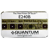
E240B QUANTUM ATMEL, E240B Datasheet

E240B
Specifications of E240B
Available stocks
Related parts for E240B
E240B Summary of contents
Page 1
E240 User Manual ™ 13 ...
Page 2
E240 16 User Manual OVERVIEW The E240 is designed to let you evaluate and develop with the QT240 4 key QTouch™ IC. It includes four independent touch sensitive electrodes with corresponding LEDs to indicate touch. Connections are provided for external ...
Page 3
BOARD MOUNTING The E240 can be adhered to plastic, glass, or any other dielectric panel with its peel-back adhesive strip. You do not have to use the supplied panel if you would rather stick it on your own panel. Here’s ...
Page 4
RUNNING THE E240 2 To run the E240, simply: 1 Place the E240 on a table, touch side up. 2 Connect the 9V battery while making sure your fingers are clear of the touch areas to allow proper no-signal calibration. ...
Page 5
THEORY OF OPERATION The E240 scans the keys using bursts of charge-transfer pulses. Immediately after power up, the signals from these bursts are used to calibrate the baseline reference values of the keys. This makes the device highly adaptive to ...
Page 6
BOARD DETAILS 4 The E240 is a simple double-sided PCB on industry standard FR4 material. All parts are standard surface mount types. Here is a brief description of some of the parts and features. Keys — Keys consists of capacitive ...
Page 7
BOARD LAYOUT Figure 1 — Board Layout Battery Connector Connector (CN1) Table 1 — Connector (CN1) Pinout Pin Description Pin 1 SYNC 5 2 OUT ‘D’ OUT ‘C’ 4 OUT ‘B’ Electrodes (on user side) ...
Page 8
SCHEMATIC 6 Figure 2 — Schematic Diagram 7 ...
Page 9
PCB LAYERS 8 Figure 3 — Silk Layer Figure 4 — Top Layer (user side) ...
Page 10
BOARD OPTIONS Warning: Changing components on the board involves soldering and unsoldering; please take care not to overheat the board or to leave excessive flux which can affect signal stability and performance doubt, clean the board with a ...
Page 11
OPTION JUMPERS 10 Jumpers 1, 2 and 3 set the mode to Fast (40msec response) or Slow (110msec response), Spread Spectrum, and external sync. Table 2 — Jumpers Fast, Slow, Spread Spectrum Modes Description JMP 1 Fast ...
Page 12
SENSITIVITY The sensitivity of the keys has been tailored to match the supplied plastic panel. To make a key more sensitive, increase the value of its corresponding Cs capacitor (see chart below). To make it less sensitive, decrease it’s Cs ...
Page 13
SPREAD SPECTRUM 12 With Spread Spectrum enabled (factory default configuration), a sawtooth voltage signal is generated on pin 9 (SYNC/SS) of the QT240; this is used to modulate the QT240’s burst frequency. As pin 9 ramps up, the sample burst ...
Page 14
TROUBLESHOOTER Does Not Power supply too low or connected backwards Work Keys Not Keys not calibrated properly Sensitive Recalibrate or let stand for seconds to let drift compensation work Enough on the references Cs values need to ...
Page 15
Development Team: Luben Hristov, Peter Dennis, Matthew Trend Corporate Headquarters North America 1 Mitchell Point 651 Holiday Drive Bldg 300 Ensign Way, Hamble Pittsburgh, ...


