6-201 COMPLEMENTARY TECHNOLOGIES, 6-201 Datasheet

DRIVER BOARD, LCD

6-201

Manufacturer Part Number
6-201
Description
DRIVER BOARD, LCD
Manufacturer
COMPLEMENTARY TECHNOLOGIES
Type
LCD Driver Boar
Datasheet

Specifications of 6-201

Development Tool Type
LCD Driver Board
Kit Features
2400 Or 9600 Baud Rate, Compatible With Hitachi 44780 Controllers, Up To 80 On-Screen Characters
Tool / Board Applications
LCD Display
Silicon Manufacturer
Complementary Technologies
Kit Contents
Board
Core Architecture
Display
Core Sub-architecture
LCD
MILFORD INSTRUMENTS Ltd
This note accompanies the following products:
BPK LCD Driver Board- Part Number 6-201,
Serial LCD 2x16, Part number 6-111
Serial LCD 2x20, Part number 6-121
Serial LCD 2x40, Part number 6-131
Serial LCD 4x20, Part number 6-141.
Suitability
The BPK Serial Driver Board is a daughterboard that attaches to LCD modules and converts
the standard 4 or 8-bit parallel interface to a more easily managed serial interface at either
2,400 or 9,600 baud. It is compatible with all Hitachi 44780 controllers (or equivalents by OKI,
Samsung etc) with up to 80 on-screen characters. It is not suitable for 4x40 displays.
Connecting the BPK Board
LCD Connection- Non Backlit LCDs
The BPK board is supplied with SIL and DIL connectors- select the most appropriate connector
for your LCD. Non-backlit LCDs will have either a 14x1 pin or 7x2 pin arrangement- the
supplied connectors are 16x1 and 8x2- trim these down to suit the LCD.
Solder the selected connector to the BACK (component, non-display side) of the LCD using
the shorter length pins. Place the two double-sided foam pads on the back of the LCD to
prevent the LCD and driver boards from touching. Position the driver board over the header-
ensure that pin 1 is connected to pin 1 and that BPK pins 15 and 16 remain un-connected.
Solder in place
LCD Connection- LCDs with Backlighting
The BPK board is supplied with SIL and DIL connectors- select the most appropriate connector
for your LCD. Backlit LCDs will have either a 16x1 pin or 8x2 pin arrangement- the BPK board
assumes the back-lighting will be connected to pins 15 (Anode) and 16 (Kathode) – check
this configuration is correct before proceeding further.
Solder the selected connector to the BACK (component, non-display side) of the LCD using
the shorter length pins. Place the two double-sided foam pads on the back of the LCD to
prevent the LCD and driver boards from touching. Position the driver board over the header-
ensure that pin 1 is connected to pin 1. Solder in place
Connecting up the Driver Board/LCD
The Driver Board requires just 3 connections, incoming signal, ground and +5v at
approximately 2mA (excluding back-lighting) making it suitable for driving from either of the
BASIC Stamps.
DB-9 Socket
Connect the signal line to pin 3 and ground to pin 5. Some PC software requires handshaking
so you may need to make the following connections:
1 to 4 to 6
7 to 8
DB-25 Socket
Connect the signal line to pin 2 and ground to pin 7. Additional connections that may be
needed are:
Pin 4 to 5
Reg Office:
Reg Number: 4222329
Reg Office
Reg Number
:
: 4222329
Milford House, 120 High Street, South Milford, LEEDS LS25 5AQ
BPK LCD Driver Board Part # 6-201
Pin 6 to 8 to 20.
Tel: 01977 683665
Tel: 01977 683665
Fax 01977 681465
Fax 01977 681465
United Kingdom
United Kingdom
Rev 1.1 24/4/01
www.milinst.com
www.milinst.com

Related parts for 6-201

6-201 Summary of contents

Page 1

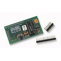
... MILFORD INSTRUMENTS Ltd BPK LCD Driver Board Part # 6-201 This note accompanies the following products: BPK LCD Driver Board- Part Number 6-201, Serial LCD 2x16, Part number 6-111 Serial LCD 2x20, Part number 6-121 Serial LCD 2x40, Part number 6-131 Serial LCD 4x20, Part number 6-141. ...

Page 2

... Power for the back-lighting is supplied via the 3-pin header. The back-lighting is selected On or OFF by the B/L jumper. The back-lighting current is set by resistor RBL to approximately 200mA (0.8V/3R9) or 170mA (0.8V/4R7) for the 6-111 and 6-201 products. RBL may be adjusted to suit particular LCDs but always ensure the maximum back-lighting current is not exceeded ...

Page 3

... To define one of the 8 characters in CG RAM, put the LCD into Instruction mode, then send the following value to the LCD: 64 character_no.) where character_no the range Then send the bit-map data calculated as shown above. For example to define CG RAM 3 with the above character send the following byte string: [254, 88,0,4,14,31,14,4,0,0] where 88 is calculated from 64 ...

Page 4

... Line 2 address address 192 193 194 195 196……...231 4x20 LCD Line 1 address address: 128 129 130 131 132 ……..147 Line 2 address address 192 193 194 195 196……...211 Line 3 address address: 148 149 150 151 152 ……..167 ...

Related keywords