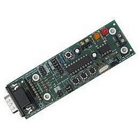
EB018 MATRIX, EB018 Datasheet - Page 8

EB018
Manufacturer Part Number
EB018
Description
E-blocks CAN Bus Board
Manufacturer
MATRIX
Datasheet
1.EB018.pdf
(9 pages)
Specifications of EB018
Silicon Manufacturer
Matrix
Application Sub Type
CAN Bus
Kit Application Type
Interface
Silicon Core Number
MCP2515 And MCP2551
Kit Contents
Board
Rohs Compliant
Yes
Lead Free Status / RoHS Status
Lead free / RoHS Compliant
3. Jumper settings
4. Using Microcontrollers with embedded CAN
5. 3.3V operation
The design of this product enables you to use this boarde with many standard PICmicro devices. This is achieved
by identifying the up-stream device, then selecting the corresponding jumper setting on the CAN board. This will
configure the board with the correct pin-out for the PICmicro selected. Jumper setting A, B, and C are used for
selecting the appropriate pins for SDO, SDI and SCK: the dedicated SPI lines. Jumper settings 1 and 2 are used to
set the correct pins for /CS and /INT.
The microcontroller that is being used determines which port and which jumper. For example, if an PIC16F877A is
being used, the CAN Board must be connected to Port A, with the jumper settings to A & 1.
The following tables illustrate the correct jumper settings:
The following table (Table 2) shows the settings that can be used for /CS and /INT:
The Patch System allows the user to route SDO, SDI, SCK, /CS and /INT to any of the 8 input bits required. This
allows great flexibility, as the user can then use a different device other than those specified in Table 1. When using
the CAN Board with up-stream devices that are not mentioned in the above table, such as Atmel AVR® Board or
other processor boards, then the patch system will be required.
transceiver chip such as the MCP2551 on this E-Block. Such microcontrollers can use the transceiver chip on this E-
Block by removing the MCP2515 controller chip and using the patch system to link the appropriate TXCAN and
RXCAN pins of the microcontroller to pins 1 and 2 of the vacated MCP2515 socket.
This board is not compatible with 3.3V systems.
Copyright © Matrix Multimedia Limited 2005
Some microcontrollers have an inbuilt CAN module, but these still need to be interfaced to the CAN bus using a
PIC16F devices
PIC16F873/A
PIC16F874/A
PIC16F876/A
PIC16F877/A
PIC16F737
PIC16F747
PIC16F767
PIC16F777
PIC16F872
PIC16F72
PIC16F73
PIC16F74
PIC16F76
PIC16F77
Bit 6
/CS
CONNECT BOARD TO PORT C
Jumper Setting
Jumper Setting
1
A
PIC16C devices
Bit 0
/INT
PIC16C62B
PIC16C63A
PIC16C72A
PIC16C73B
PIC16C74B
PIC16C773
PIC16C774
PIC16C65
PIC16C66
PIC16C67
PIC16C76
PIC16C77
Table 1. Jumper settings for SDO, SDI & SCK selection.
Table 2. Jumper settings for /INT and /CS selection
CONNECT BOARD TO PORT B
Patch
/CS
Jumper Setting
Jumper Setting
PIC16F818
PIC16F819
PIC16F87
PIC16F88
B
2
Patch
/INT
PATCH SYSTEM
Jumper Setting
E-blocks™ CAN bus board
C
Document code: EB018-30-1
page 8


