ADXL203EB Analog Devices Inc, ADXL203EB Datasheet
ADXL203EB
Manufacturer Part Number
ADXL203EB
Description
±1.7g Dual-Axis IMEMS Accelerometer Evaluation Board
Manufacturer
Analog Devices Inc
Series
iMEMS®r
Specifications of ADXL203EB
Silicon Manufacturer
Analog Devices
Application Sub Type
Accelerometer - Dual-Axis
Kit Application Type
Sensing - Motion / Vibration / Shock
Silicon Core Number
ADXL203
Sensor Type
Accelerometer, 2 Axis
Sensing Range
±1.7g
Interface
Analog
Sensitivity
1000mV/g
Voltage - Supply
3 V ~ 6 V
Embedded
No
Utilized Ic / Part
ADXL203
Lead Free Status / RoHS Status
Contains lead / RoHS non-compliant
Other names
Q1875695


GENERAL DESCRIPTION
The ADXL203EB is a simple evaluation board that allows quick
evaluation of the performance of the ADXL203 dual axis ±1.7 g
accelerometer. The ADXL203EB has a 5-pin 0.1 inch spaced
header for access to all power and signal lines that the user can
attach to a prototyping board (breadboard) or wire using a
standard plug. Four holes are provided for mechanical attach-
ment of the ADXL203EB to the application.
The ADXL203EB is 20 mm × 20 mm, with mounting holes set
15 mm × 15 mm at the corners of the PCB.
CIRCUIT DESCRIPTION
The schematic and parts list of the ADXL203EB are shown in
Figure 1. Analog bandwidth can be set by changing capacitors
C2 and C3. See the ADXL203 data sheet for a complete descrip-
tion of the operation of the accelerometer.
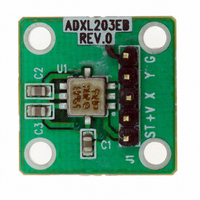
The part layout of the ADXL203EB is shown in Figure 2. The
ADXL203EB has two factory-installed 100 nF capacitors (C2
and C3) at X
Many applications require a different bandwidth, in which case
the user can change C2 and C3, as appropriate.
SPECIAL NOTES ON HANDLING
The ADXL203EB is not reverse polarity protected. Reversing
the +V supply and ground pins can cause damage to the
ADXL203.
Dropping the ADXL203EB on a hard surface can generate
several thousand g of acceleration and might exceed the data
sheet absolute maximum limits. See the ADXL203 data sheet for
more information.
Rev. 0
Information furnished by Analog Devices is believed to be accurate and reliable.
However, no responsibility is assumed by Analog Devices for its use, nor for any
infringements of patents or other rights of third parties that may result from its use.
Specifications subject to change without notice. No license is granted by implication
or otherwise under any patent or patent rights of Analog Devices. Trademarks and
registered trademarks are the property of their respective owners.
OUT
and Y
OUT
to reduce the bandwidth to 50 Hz.
ORDERING GUIDE
Model
ADXL203EB
One Technology Way, P.O. Box 9106, Norwood, MA 02062-9106, U.S.A.
Tel: 781.329.4700
Fax: 781.326.8703
0.1µF
C1
Dual Axis Accelerometer
C2
C3
ADXL203
Figure 2. ADXL203EB Physical Layout
TOP VIEW
PIN 1
Figure 1. ADXL203EB Schematic
© 2004 Analog Devices, Inc. All rights reserved.
ADXL203EB
REV. 0
203CE
Evaluation Board
Package Description
Evaluation Board
C1
C2
0.1µF
ADXL203EB
C3
0.1µF
J1
www.analog.com
SELF TEST
V
X
Y
COMMON
DD
OUT
OUT
G
Y
X
+V
ST
Related parts for ADXL203EB
Image
Part Number
Description
Manufacturer
Datasheet
Request
R

Part Number:
Description:
Analog MCU Evaluation Board
Manufacturer:
Analog Devices Inc
Datasheet:
Part Number:
Description:
Inertial Sensor Evaluation System
Manufacturer:
Analog Devices Inc
Datasheet:
Part Number:
Description:
Manufacturer:
Analog Devices Inc
Datasheet:
Part Number:
Description:
Manufacturer:
Analog Devices Inc
Datasheet:
Part Number:
Description:
Manufacturer:
Analog Devices Inc
Datasheet:
Part Number:
Description:
Manufacturer:
Analog Devices Inc
Datasheet:
Part Number:
Description:
Manufacturer:
Analog Devices Inc
Datasheet:
Part Number:
Description:
Manufacturer:
Analog Devices Inc
Datasheet:
Part Number:
Description:
Manufacturer:
Analog Devices Inc
Datasheet:
Part Number:
Description:
Manufacturer:
Analog Devices Inc
Datasheet:
Part Number:
Description:
Manufacturer:
Analog Devices Inc
Datasheet:
Part Number:
Description:
Manufacturer:
Analog Devices Inc
Datasheet:
Part Number:
Description:
Manufacturer:
Analog Devices Inc
Datasheet:
ADXL203EB Summary of contents
Page 1
... The schematic and parts list of the ADXL203EB are shown in Figure 1. Analog bandwidth can be set by changing capacitors C2 and C3. See the ADXL203 data sheet for a complete descrip- tion of the operation of the accelerometer. The part layout of the ADXL203EB is shown in Figure 2. The ADXL203EB has two factory-installed 100 nF capacitors (C2 and C3 and Y to reduce the bandwidth ...
Page 2
... ADXL203EB © 2004 Analog Devices, Inc. All rights reserved. Trademarks and registered trademarks are the property of their respective owners. D04837–0–4/04(0) Rev Page ...