12C SUPERIOR ELECTRIC, 12C Datasheet - Page 2
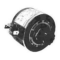
12C
Manufacturer Part Number
12C
Description
Variable Transformer
Manufacturer
SUPERIOR ELECTRIC
Type
Variabler
Specifications of 12C
Input Voltage
240V
Output Current
0.7A
Knob Rotation
CW / CCW
Transformer Mounting
Panel
Secondary Current Nom
0.7A
No. Of Phases
Single
Primary Voltages
240V
Power Rating
0.17kVA
Brand/series
Powerstat®/12C Series
Configuration
Open Frame
Current, Secondary
0.7/0.5 A
Dimensions
2.06"L×2.81"Dia.
Frequency
50/60 Hz
Mounting Type
Panel/Chassis
Number Of Outlets
1
Phase
1
Power, Rating
0.17/0.13 kVA (Constant Current Load), 0.22 kVA (Constant Impedance Load)
Termination
Quick-Connect
Voltage, Primary
240 VAC
Voltage, Secondary
0-240/0-264 VAC
Constant Current Load
70mA
Rohs Compliant
Yes
Current Rating
0.7A
Output Voltage
240V
Output Voltage Max
240VAC
Lead Free Status / RoHS Status
Lead free / RoHS Compliant
Available stocks
Company
Part Number
Manufacturer
Quantity
Price

Part Number:
12C508
Manufacturer:
ST
Quantity:
20 000
Part Number:
12C508-04/SM
Manufacturer:
MICROCHIP/微芯
Quantity:
20 000
Part Number:
12C508-SN
Manufacturer:
SN
Quantity:
20 000
Company:
Part Number:
12C508/P
Manufacturer:
MICROCHIP
Quantity:
5 510
Company:
Part Number:
12C508/P
Manufacturer:
LITTLEFUSE
Quantity:
5 510
Company:
Part Number:
12C508A
Manufacturer:
SAWTEK
Quantity:
350
Company:
Part Number:
12C508A-04/P
Manufacturer:
MIC
Quantity:
6 259
Company:
Part Number:
12C508A-04/PHBP
Manufacturer:
AMSI
Quantity:
6 229
Part Number:
12C508A-04/SM
Manufacturer:
MICREL/麦瑞
Quantity:
20 000
Part Number:
12C508A04
Manufacturer:
MIC
Quantity:
20 000


50/60
50/60
50/60
50/60
50/60
50/60
Freq.
Freq.
Freq.
Freq.
Freq.
Freq.
Freq.
Freq.
(Hz)
(Hz)
(Hz)
(Hz)
(Hz)
(Hz)
(Hz)
(Hz)
60
60
60
Output Voltage:
Output Voltage:
Output Voltage:
Output Voltage:
Output Voltage:
Output Voltage:
Output Voltage:
Output Voltage:
Input Voltage:
Input Voltage:
Input Voltage:
Input Voltage:
Input Voltage:
Input Voltage:
Input Voltage:
Input Voltage:
POWERSTAT Variable Transformers of the 10C, 10C-40 and 12C Series may be connected
to suit various requirements as shown in the RATINGS CHART. The individual units in
types 10C-40-2 and 10C-40-3 are not electrically interconnected but are independently
wired following the type 10C-40 connections. Under “KNOB ROTATION”, rotating the
knob in the direction indicated will INCREASE the output voltage. The dial is marked for
clockwise rotation only.
Amps
Amps
Amps
Amps
Amps
Amps
Amps
Amps
Max.
Max.
Max.
Max.
Max.
Max.
Max.
Max.
Current Load
Current Load
2.25
Current Load
2.25
Current Load
Current Load
2.25
Current Load
Current Load
2.25
Current Load
0.7
0.7
0.7
0.7
7
Constant
Constant
Constant
Constant
Constant
Constant
Constant
Constant
• Jumper provided in standard common position should be moved or removed as
• 10C type ratings are when unit(s) are mounted on a metal panel. When mounted
• 12C type ratings are when unit(s) are mounted on a metal panel. When mounted
• Fuses are recommended (not supplied) on all units as shown ( § ).
• COMMON shown in the CONNECTION DIAGRAMS is used as third leg in 3-phase
CONNECTIONS AND RATINGS
Important connection notes. Please read carefully.
required.
on a bracket or nonmetallic panel, derate to 1.75 amperes for Constant Current
Load and 2.5 amperes for Constant Impedance Load.
on a bracket or nonmetallic panel, derate to 0.5 amperes for Constant Current Load
and 0.75 amperes for Constant Impedance Load.
open delta, or neutral in single-phase 3-wire and 3-phase 4-wire wye configurations.
COMMON is not used in single-phase 2-wire or 3-phase 3-wire wye configurations.
Jumper(s) provided in standard common position should be moved or removed as
required.
Max.
0.28
Max.
0.27
Max.
0.17
0.54
Max.
0.29
Max.
0.47
Max.
0.29
Max.
0.94
Max.
0.58
KVA
KVA
KVA
KVA
KVA
KVA
KVA
KVA
“LINE” CONNECTION
“LINE” CONNECTION
“LINE” CONNECTION
“LINE” CONNECTION
“LINE” CONNECTION
“LINE” CONNECTION
“LINE” CONNECTION
“LINE” CONNECTION
Impedance Load
Impedance Load
Impedance Load
Impedance Load
Impedance Load
Impedance Load
Impedance Load
Impedance Load
Amps
Amps
Amps
Amps
Amps
Amps
Amps
Amps
0-120
0-240
0-480
0-120
0-240
0-240
0-480
Max.
Max.
Max.
Max.
Max.
Max.
Max.
Max.
0-40
120
240
0.9
480
0.9
120
240
0.9
240
480
0.9
40
9
3
3
3
3
120 VOLT, THREE PHASE OPEN DELTA
240 VOLT, THREE PHASE OPEN DELTA
Constant
Constant
Constant
Constant
Constant
Constant
Constant
Constant
240Y / 138 VOLT, THREE PHASE WYE
480Y / 277 VOLT, THREE PHASE WYE
Max.
Max.
Max.
Max.
Max.
Max.
Max.
Max.
KVA
0.36
KVA
0.36
KVA
0.22
0.72
KVA
0.37
KVA
0.62
KVA
0.37
KVA
KVA
0.75
1.2
RATINGS CHART
2-1-2
1-2-1
2-1-2
1-2-1
2-2-2
1-1-1
2-2-2
1-1-1
Input
CCW
Input
CCW
0-208
Input
CCW
0-380
Input
CCW
Input
CCW
0-208
Input
CCW
0-208
Input
CCW
0-380
Input
CCW
CW
1-2
1-2
CW
1-2
1-2
208
CW
380
CW
2-2
1-1
CW
208
CW
208
CW
380
CW
1-2
1-2
2-2
1-1
120 VOLT, SINGLE PHASE
240 VOLT, SINGLE PHASE
480 VOLT, SINGLE PHASE
40 VOLT, SINGLE PHASE
Terminals & Rotation
Terminals & Rotation
Terminals & Rotation
Terminals & Rotation
Terminals & Rotation
Terminals & Rotation
Terminals & Rotation
Terminals & Rotation
Output
Output
Output
Output
Output
Output
Output
Output
3-1-3
3-2-3
3-1-3
3-2-3
3-3-3
3-3-3
3-3-3
3-3-3
CCW
CCW
CCW
CCW
CCW
CCW
CCW
CCW
CW
1-3
2-3
CW
1-3
2-3
CW
1-3
2-3
3-3
3-3
CW
3-3
3-3
CW
CW
CW
CW
Jumper
Jumper
Jumper
Jumper
Jumper
Jumper
Jumper
Jumper
CCW
CCW
CCW
CCW
CCW
CCW
CCW
1-1-1
2-2-2
CCW
1-1-1
2-2-2
CW
CW
CW
CW
CW
CW
CW
CW
1-1
2-2
1-1
2-2
1-1
2-2
1-1
2-2
0-132
0-264
50/60
0-528
0-132
0-264
0-528
Freq.
Freq.
Freq.
Freq.
50/60
Freq.
Freq.
50/60
Freq.
Freq.
(Hz)
(Hz)
(Hz)
(Hz)
(Hz)
(Hz)
(Hz)
(Hz)
120
240
480
120
240
480
60
60
60
60
Amps
Amps
Amps
Amps
Amps
Amps
Amps
Amps
Max.
Max.
Max.
Max.
Max.
Max.
Max.
Max.
Current Load
Current Load
2.25
Current Load
2.25
Current Load
Current Load
2.25
Current Load
Current Load
Current Load
0.7
0.7
0.7
0.7
Constant
Constant
Constant
Constant
Constant
Constant
Constant
Constant
“BOOST” CONNECTION
“BOOST” CONNECTION
“BOOST” CONNECTION
“BOOST” CONNECTION
“BOOST” CONNECTION
“BOOST” CONNECTION
“BOOST” CONNECTION
“BOOST” CONNECTION
0-228
0-418
0-228
0-418
Max.
KVA
Max.
KVA
208
Max.
KVA
0.13
0.59
Max.
KVA
Max.
KVA
Max.
KVA
Max.
KVA
Max.
KVA
0.3
380
0.26
0.51
208
0.23
380
0.46
Input
Input
Input
Input
Input
Input
Input
Input
CCW
CCW
CCW
CCW
CCW
4-1-4
CCW
4-4-4
CCW
CCW
4-4-4
CW
CW
1-4
CW
1-4
4-4
CW
CW
CW
CW
CW
4-4
-
-
-
-
-
-
-
Terminals & Rotation
Terminals & Rotation
Terminals & Rotation
Terminals & Rotation
Terminals & Rotation
Terminals & Rotation
Terminals & Rotation
Terminals & Rotation
Output
Output
Output
Output
Output
Output
Output
Output
CCW
CCW
CCW
CCW
CCW
3-1-3
CCW
3-1-3
CCW
CCW
3-3-3
CW
CW
1-3
CW
1-3
3-3
CW
CW
CW
CW
CW
3-3
-
-
-
-
-
-
-
Jumper
Jumper
Jumper
Jumper
Jumper
Jumper
Jumper
Jumper
CCW
CCW
CCW
CCW
CCW
CCW
CCW
CCW
1-1-1
CW
CW
CW
1-1
CW
1-1
CW
1-1
CW
1-1
CW
CW
-
-
-
-
-
Manually
Operated
Manually
Operated
Manually
Operated
Manually
Operated
Manually
Operated
Manually
Operated
Manually
Operated
Numbers
Numbers
Numbers
Numbers
Numbers
Numbers
Numbers
Numbers
Manually
Operated
10C-40
10C-2
12C-2
10C-2
12C-2
10C-3
12C
Model
Model
10C
Model
Model
Model
Model
Model
Model
12C-3
Conn.
Conn.
Conn.
Conn.
Conn.
Conn.
Conn.
Conn.
Diag.
Diag.
Diag.
Diag.
Diag.
Diag.
Diag.
Diag.
20
21
21
22
22
22
22
23
23
Viewed from Knob End
PANEL DRILLING TEMPLATE
#20
#22
Ganged Assemblies
(Viewed from Knob End)
CONNECTION
(Viewed from Knob End)
DIAGRAMS
#21
#23
Related parts for 12C
Image
Part Number
Description
Manufacturer
Datasheet
Request
R

Part Number:
Description:
Transformer; Variable Ctrl; 1 Phase, 3 Phase Open Delta; 0.7A Io; 0.29kVA; 240V Vo
Manufacturer:
SUPERIOR ELECTRIC
Datasheet:
Part Number:
Description:
Transformer; Variable Ctrl; Pri: 0 to 480V, Sec: 0 to 528V; 3 Phase Open Delta; Knob
Manufacturer:
SUPERIOR ELECTRIC
Datasheet:
Part Number:
Description:
Replacement Brush For Superior Electric 126 Series Transformers
Manufacturer:
SUPERIOR ELECTRIC
Datasheet:

Part Number:
Description:
Variable Transformer
Manufacturer:
SUPERIOR ELECTRIC
Datasheet:

Part Number:
Description:
Variable Transformer
Manufacturer:
SUPERIOR ELECTRIC
Datasheet:
Part Number:
Description:
Variable Transformer
Manufacturer:
SUPERIOR ELECTRIC
Datasheet:

Part Number:
Description:
Variable Transformer
Manufacturer:
SUPERIOR ELECTRIC
Datasheet:

Part Number:
Description:
Variable Transformer
Manufacturer:
SUPERIOR ELECTRIC
Datasheet:

Part Number:
Description:
Variable Transformer
Manufacturer:
SUPERIOR ELECTRIC
Datasheet:
Part Number:
Description:
Variable Transformer
Manufacturer:
SUPERIOR ELECTRIC
Datasheet:
Part Number:
Description:
Variable Transformer
Manufacturer:
SUPERIOR ELECTRIC
Datasheet:
Part Number:
Description:
STABILINE Full Range Regulator Microprocessor Control, 1 Channel
Manufacturer:
SUPERIOR ELECTRIC

Part Number:
Description:
Surge Suppressor
Manufacturer:
SUPERIOR ELECTRIC
Datasheet:
Part Number:
Description:
#21U TYPE 21-117 VARIAC 5 AMMP 120V INPUT TRANSISTOR
Manufacturer:
SUPERIOR ELECTRIC