CPS-BRACKET Honeywell Sensing and Control, CPS-BRACKET Datasheet

Mounting Bracket

CPS-BRACKET

Manufacturer Part Number
CPS-BRACKET
Description
Mounting Bracket
Manufacturer
Honeywell Sensing and Control
Datasheet

Specifications of CPS-BRACKET

For Use With
CPS Series
Lead Free Status / RoHS Status
Lead free / RoHS Compliant
CPS Series
Cable Pull Safety Switch
FEATURES
• Direct opening action
• 2CPS: 2NO/2NC, 1NO/3NC or 4NC
• Typical cable span of 76 m (250 ft) in an
• Choice of three actuator configurations
• Removable contact block version
• Large wiring cavity with straight-
• 24 Vdc or 120 Vac bright, multicluster
• Gold-plated contacts are standard on
• Die-cast zinc housing
• Optional hardware packs available
TYPICAL APPLICATIONS
• Long conveyor systems found in
• Conveyor systems having a high amount
• Conveyor systems that experience wide
• Long conveyor systems where easy
• Hose down conditions
• Packaging equipment
• Assembly lines
© Honeywell International Inc. - April 2003
(normally closed) contacts
contact configurations
1CPS: 1NO/1NC, 2NO/2NC, 1NO/3NC or
4NC contact configurations
environment with a temperature change
of ±17 °C (±30 °F). Longer spans are
possible depending upon temperature
change and installation
(ref. note on page 6 for more details or
Application note - Effect of Temperature
on Cable Pull Switch Operation)
(2CPS)
available (2CPS)
through wiring
LED status indicator light available on
2CPS. Single high intensity LED on 1CPS
2CPS, available on 1CPS
warehouses and distribution centers
of vibration
temperature swings
through wiring, or highly visible trip
status is required
of NC
• Safety Products for Machine Safeguarding •
(Applied for)
CPS Series Cable Pull Safety Switches provide a readily accessible emergency stop
signal. This is a cost-effective means compared to using multiple emergency stop
push-buttons. (Cable Pull Safety Switches are not, however, to be used as a means
of personnel safeguarding. They may be used to prevent further injury or damage to
equipment when used for emergency stop signaling.)
The CPS Series Cable Pull Safety switch is designed to provide emergency stop
protection for exposed conveyor and assembly lines. The internal mechanism
latches on both slackened cable (push) and pulled cable. This capability also en-
hances productivity by eliminating nuisance stops due to variations in temperature,
stretch of cable over time, and other application variables.
The 1CPS is intended for use in applications where the cable span is 76 m (250 ft)
or shorter. It is an economical solution for shorter runs or zone protection typical to
automated systems. The 2CPS series is intended for use in very long cable runs of
152 m (500 ft) or shorter, such as long conveyor lines found in warehouses.
A line in the midpoint of the cable tension window indicates proper cable tension,
providing easy set-up. The direct opening switch contacts are held closed when the
actuating cable is under proper tension and the reset knob is set to RUN. When the
actuating cable is pulled, slackened or broken, a cam positively opens the NC (Nor-
mally Closed) switch contacts. The snap action, trip operation causes the switch
contacts to change state and mechanically latch almost simultaneously when the
cable is pulled, slackened or broken. The NC switch contacts remain open until the
CPS is reset by properly tensioning the cable and manually rotating the reset knob.
When the direct opening switch contacts open, the auxiliary contacts also actuate
(open contacts close and closed contacts open). The auxiliary contacts are electri-
cally isolated from the direct opening switch contacts. These NO (Normally Open)
contacts may be used for monitoring or signaling.
The CPS complies with: Low Voltage Directive 73/23/EEC, as amended by directive
93/68/EEC; Machinery Directive 98/37/EEC only as the directives relate to the
components being used in a safety function; IEC/EN 60947-1; IEC/EN 60947-5-1;
IEC/EN 60947-5-5.
BG
MISUSE OF DOCUMENTATION
• The information presented in this product sheet (or catalogue) is for reference only. DO NOT USE this document as system
• Complete installation, operation and maintenance information is provided in the instructions supplied with each product.
Failure to comply with these instructions could result in death or serious injury.
!
installation information.
WARNING
1

Related parts for CPS-BRACKET

CPS-BRACKET Summary of contents

Page 1

... The 1CPS is intended for use in applications where the cable span (250 ft) or shorter economical solution for shorter runs or zone protection typical to automated systems. The 2CPS series is intended for use in very long cable runs of 152 m (500 ft) or shorter, such as long conveyor lines found in warehouses ...

Page 2

... UL & CSA BG Applied for Vibration 500 Hz Shock 15 g Contact Silver standard material Gold plated optional Included None accessories Conduit Thread A = 1/2" NPT Ordering: 1CPS X Example: 1CPSA1A 2 1 NORMALLY CLOSED/ 1 NORMALLY OPEN *9 (0.39) 12,7 7,9 3,8 3,8 7,9 (0.50) (0.31) (0.15) (0.15) (0 ...

Page 3

NORMALLY CLOSED/ 1 NORMALLY OPEN *9,9 *9 (0.39) (0.39) 12,7 7,9 3,8 3,8 7,9 12,7 (0.50) (0.31) (0.15) (0.15) (0.31) (0.50) 21-22 A 13-14 11-12 B 21-22 ...

Page 4

... DC13 Q300 UL & CSA BG Vibration 500 Hz Shock 15 g Contact Gold plate material over silver Included Turnbuckle(s) accessories Conduit Thread A 1/2" NPT = Ordering: 2CPS X Example: 2CPSA1A2B 4 2 NORMALLY CLOSED/ 2 NORMALLY OPEN *9,9 0 (0.39) 12,7 7,9 3,8 (0.50) (0.31) (0.15) 21-22 A 13-14 21-22 B ...

Page 5

NORMALLY CLOSED *9,9 *9 (0.39) (0.39) 12,7 7,9 3,8 3,8 7,9 12,7 (0.50) (0.31) (0.15) (0.15) (0.31) (0.50) 11-12 A 21-22 11-12 B 21- ...

Page 6

... Install the system when the temperature is at the mid point of the extremes warehouse has a low temperature of 15,6 °C (60 °F) and a high of 32,2 °C (90 °F), set up the system at the midpoint 23,9 °C (75 °F). Use an endspring or another CPS at the opposite end of the cable span to double the temperature tolerance and to meet the requirements of EN 418. ...

Page 7

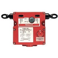
... Application information 1CPS 0,46 m [18 in] maximum B 2 ft] maximum [250 ft] typical D Reset knob 2CPS [18 in] maximum B 2 ft] maximum [250 ft] typical D J-hook turnbuckle (included) E Thimble F Cable clamp © Honeywell International Inc. - April 2003 Tension indicator line is in center of indicator window – cable is properly tensioned ...

Page 8

... A Multi-LED red pilot light B 1/2-14 NPom Thread C 18 AWG red PVC insulation D 18 AWG black PVC insulation CPS-BRACKET 8 Accessory Cable - 7,6 m (25 ft) length Cable - 15,2 m (50 ft) length Cable - 30,5 m (100 ft) length Cable - 45,7 m (150 ft) length Cable - 61 m (200 ft) length Cable - 76,2 m (250 ft) length ...

Page 9

... C 2X 26,67 [1.050] A Fully extended B Optional indicator C Conduit thread (3 total) D Mounting pad (4 total) 2CPS 40,4 (1.60) 67,8 (2.63) 325,9 A (12.75) 21,1 (0.75) 34,9 (1.38) 152,4 (6.00) 104,8 (4.13) 6,4 (0.25) 12,7 (0.50) © ...

Page 10

Warranty and remedy Honeywell warrants goods of its manufacture as being free of defective materials and faulty workmanship. Contact your local sales office for war- ranty information. If warranted goods are returned to Honeywell during the period of coverage, Honeywell ...

Related keywords