R4E310-AE05-17 EBM-Papst Industries Inc, R4E310-AE05-17 Datasheet - Page 4
R4E310-AE05-17
Manufacturer Part Number
R4E310-AE05-17
Description
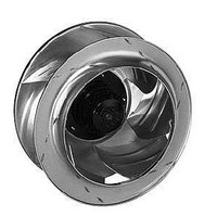
AC Backward-Curved Motorized Impeller
Manufacturer
EBM-Papst Industries Inc
Series
R4E310r
Type
Roundr
Datasheet
1.W2S130-BM15-01.pdf
(5 pages)
Specifications of R4E310-AE05-17
Weight
8 lbs (3.6kg)
Fan Type
Motorized Impellers
Size / Dimension
Round - 318mm Dia x 154mm W
Voltage Rating
230VAC
Power (watts)
165W
Noise
68 dB(A)
Air Flow
1265 CFM (35.82³/min)
Termination
2 Wire Leads
Bearing Type
Ball
Flow Rate
1330 CFM
Material, Impeller
Aluminum
Noise Level
68 dBA
Power, Rating
165 W
Voltage, Rating
230 VAC
Cable Exit
Variable. Direction of Rotation is CW as Seen from Intake Side
Recommended Inlet Ring
31051-2-4013 (Sold Separately)
Lead Free Status / RoHS Status
Lead free / RoHS Compliant
Rpm
-
Static Pressure
-
Lead Free Status / Rohs Status
Lead free / RoHS Compliant
Other names
381-2404


Prerequisites
➜ Check whether the data on the type plate agree with the connection data.
➜ Before connecting the device, ensure that the mains supply voltage
➜ Only use cables designed for current according to
Residual current operated device
Voltage control
Frequency inverter
Motor protection
Connecting cables with terminals (applicable only to devices with terminal
connection)
4/5
matches the fan voltage.
the type plate.
Only all-current-sensitive RCD protective devices
(type A) are permissible. Like frequency inverters, RCD protective
devices cannot provide personal safety while operating the device.
With open loop speed control using transformers or electronic volt-
age regulators (e.g. phase angle control), excessive current may
occur.
In addition, noises can occur with phase control, depending on the
manner in which the device is installed.
Fit sinusoidal filters that work on all poles (live-live and live-earth)
between the frequency inverter and the motor for operation with
frequency inverters.
WARNING
Device without overheating protection
The device is delivered without any automatically functioning overhe-
ating protection. The device can become hot and burn.
➜ For the version without TOP, install an additional, suitable motor
(Applicable only to devices without off-board TOPs)
CAUTION
Electrical voltage
The device is a built-in component and features no electrically isolat-
ing switch.
➜ Connect the device only to circuits that can be switched off using
➜ When working on the device, you must switch off the sys-
(Applicable only to devices with off-board TOPs)
The motors are equipped with thermal overload protectors to protect
the devices.
Check to make sure that the thermal overload protector is correctly
connected before each operation.
Failure to connect up the thermal overload protector correctly will
invalidate your right to claim damage for any defects. (Applicable
only to devices with off-board TOPs)
WARNING
Terminals and connections have voltage even in a unit that is
shut off
Electric shock
➜ Wait five minutes after disconnecting the voltage at all poles
protection switch.
an all-pole disconnecting switch.
tem/machine in which the device is installed and secure it from
being switched on again.
before touching the unit.
3.3 Checking the connections
➜ Ensure that the power is off.
➜ Secure it from being switched on again.
➜ Check the correct fit of the connecting cables.
3.4 Switching on the device
➜ Inspect the device for visible external damage and the proper function of the
➜ Apply the nominal voltage to the voltage supply.
3.5 Switching off the device
➜ Separate the device from the supply voltage.
protective features before switching it on.
WARNING
Electric voltage on cable gland
Electric shock
➜ Do not use plastic terminal boxes with metal cable glands.
WARNING
Hot motor housing
Fire hazard
➜ Ensure that no combustible or flammable materials are located
in the vicinity of the fan.
Related parts for R4E310-AE05-17
Image
Part Number
Description
Manufacturer
Datasheet
Request
R

Part Number:
Description:
IMPELLER MTRZD 318X132MM 115VAC
Manufacturer:
EBM-Papst Industries Inc
Datasheet:

Part Number:
Description:
AC Backward-Curved Motorized Impeller
Manufacturer:
EBM-Papst Industries Inc
Datasheet:
Part Number:
Description:
AC Backward-Curved Motorized Impeller
Manufacturer:
EBM-Papst Industries Inc
Datasheet:

Part Number:
Description:
AC MOTORIZED IMPELLER, 310 X 154MM, 230V
Manufacturer:
EBM-Papst Industries Inc
Datasheet:
Part Number:
Description:
AC MOTORIZED IMPELLER, 310 X 154MM, 115V
Manufacturer:
EBM-Papst Industries Inc
Datasheet:

Part Number:
Description:
AC Backward-Curved Motorized Impeller
Manufacturer:
EBM-Papst Industries Inc
Part Number:
Description:
AC Backward-Curved Motorized Impeller
Manufacturer:
EBM-Papst Industries Inc
Part Number:
Description:
115VAC 60HZ 12UF UL/CSA
Manufacturer:
EBM-Papst Industries Inc
Part Number:
Description:
AC Backward-Curved Motorized Impeller
Manufacturer:
EBM-Papst Industries Inc

Part Number:
Description:
FAN EXHAUST 119 X 25MM 230VAC
Manufacturer:
EBM-Papst Industries Inc
Datasheet:

Part Number:
Description:
FAN TUBEAXIAL 92X38MM 230VAC
Manufacturer:
EBM-Papst Industries Inc
Datasheet:

Part Number:
Description:
FAN 92 X 32MM 12VDC
Manufacturer:
EBM-Papst Industries Inc
Datasheet:

Part Number:
Description:
FAN TUBEAXIAL 40X20MM 5VDC
Manufacturer:
EBM-Papst Industries Inc
Datasheet:

Part Number:
Description:
AC Tubeaxial Fan
Manufacturer:
EBM-Papst Industries Inc
Datasheet: