M4Q045-DA13-04 EBM-Papst Industries Inc, M4Q045-DA13-04 Datasheet - Page 4
M4Q045-DA13-04
Manufacturer Part Number
M4Q045-DA13-04
Description
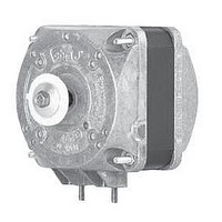
Q-Motor
Manufacturer
EBM-Papst Industries Inc
Series
M4Qr
Specifications of M4Q045-DA13-04
Fan Accessory Type
Motor for M4Q Series
Fits Fan Size
M4Q Series
Product
Fans
Lead Free Status / RoHS Status
Lead free / RoHS Compliant
Length
-
Lead Free Status / Rohs Status
Lead free / RoHS Compliant
Other names
M4Q045DA1304


Valid for all designs:
– Material: Housing made of die-cast aluminium
– Direction of air flow: "V" or "A" (depending on axial impeller used)
– Direction of rotation: Counter-clockwise, seen on shaft end
– Insulation class: "B"
– Mounting position: Any, preferrably horizontal
– Condensate discharges: None
– Mode of operation: Continuous operation (S1)
– Bearing: Self-adjusting calotte sleeve bearing (mean service life of
– Motor protection: Impedance protection (combination A-C) or thermal
– Protection class: I
Axial impellers
154
172
200
200
230
230
254
254
254
300
300
300
300
Ø D
30,000 hours in horizontal installation position)
overload protector internally switched (combination D-H)
103
123
123
123
123
135
135
135
160
160
160
160
H
90
Stator pack: Coated in black
(2) established at counterpressure of 20 Pa
108
F
61
58
58
65
64
64
64
70
76
75
75
86
Blade angle 22° ± 1°30´
104
G
56
57
58
58
62
62
62
62
74
79
79
84
27.5
31.0
32.0
32.0
35.0
35.0
37.0
37.0
37.0
43.0
43.0
43.0
43.0
C
m
1000
1000
1000
1000
3
120
190
190
500
500
580
580
580
/h
60
(2)
104
—
—
—
F
56
55
55
62
60
65
72
67
77
Blade angle 28° ± 1°30´
106
G
—
—
—
59
59
60
60
65
66
78
81
86
—
—
—
32.0
36.0
37.5
37.5
43.0
45.0
45.0
53.5
53.5
53.5
C
– Mounting: Guard grille and wall ring are mounted onto the protruding
– Axial impeller mounting: Mounted to the motor shaft using a plastic
– Power specifications: At 60 Hz, the blade angle of the axial impellers
m
thread ends of the A side. The Q-motor can also be screwed on via the
mounting flanges (integrated in the bearing shields).
adapter with pulling peg and an M4 screw (combination A-D) or M5
(combination E-H) screw.
must be reduced by 6° each.
1400
1400
1400
3
100
180
300
300
630
840
840
/h
—
—
—
(2)
—
—
—
—
—
—
—
F
54
53
59
52
67
95
Blade angle 34° ± 1°30´
112
G
62
63
—
64
—
68
—
—
80
—
—
—
37.0
42.0
—
45.0
—
50.0
—
—
52.0
—
—
—
61.0
C
m
1070
1700
3
140
230
400
820
/h
—
—
—
—
—
—
—
(2)
303
Related parts for M4Q045-DA13-04
Image
Part Number
Description
Manufacturer
Datasheet
Request
R

Part Number:
Description:
MOTOR 4POLE 5W 83X74MM 230VAC
Manufacturer:
EBM-Papst Industries Inc
Datasheet:
Part Number:
Description:
MOTOR 4POLE 8W 83X81MM 115VAC
Manufacturer:
EBM-Papst Industries Inc
Datasheet:
Part Number:
Description:
MOTOR 4POLE 9W 83X81MM 230VAC
Manufacturer:
EBM-Papst Industries Inc
Datasheet:

Part Number:
Description:
MOTOR 4POLE 16W 83X86MM 115VAC
Manufacturer:
EBM-Papst Industries Inc
Datasheet:
Part Number:
Description:
MOTOR 4POLE 18W 83X93MM 115VAC
Manufacturer:
EBM-Papst Industries Inc
Datasheet:
Part Number:
Description:
MOTOR 4POLE 26W 83X103MM 115VAC
Manufacturer:
EBM-Papst Industries Inc
Datasheet:

Part Number:
Description:
Q-Motor
Manufacturer:
EBM-Papst Industries Inc
Datasheet:
Part Number:
Description:
Q-Motor
Manufacturer:
EBM-Papst Industries Inc
Datasheet:

Part Number:
Description:
FAN EXHAUST 119 X 25MM 230VAC
Manufacturer:
EBM-Papst Industries Inc
Datasheet:

Part Number:
Description:
FAN TUBEAXIAL 92X38MM 230VAC
Manufacturer:
EBM-Papst Industries Inc
Datasheet:

Part Number:
Description:
FAN 92 X 32MM 12VDC
Manufacturer:
EBM-Papst Industries Inc
Datasheet:

Part Number:
Description:
FAN TUBEAXIAL 40X20MM 5VDC
Manufacturer:
EBM-Papst Industries Inc
Datasheet:

Part Number:
Description:
AC Tubeaxial Fan
Manufacturer:
EBM-Papst Industries Inc
Datasheet: