PRECISION COMPRESSION MOUNTING CLAMP SYSTEMS
Wakefield Engineering compression pack heat sinks and clamp systems provide electrical and
industrial equipment manufacturers with complete system solutions for proper installation
and heat dissipation for high-power compression pack semiconductor. All components for
All other products, please contact factory for price, delivery, and minimums.
144 Series
These high-quality mounting clamp assemblies are the worldwide standard for mounting,
compression, and clamping press-pack SCR, thyristor, rectifier, and other high power disc
packaged devices utilized in power distribution equipment, industrial controls, transportation
systems, and power supply and conversion systems.
Clamp assemblies will accommodate devices with overall case diameters to 5.25 in. (133.4
mm) maximum. Vertical device mounting space available for assemblies is determined by
selecting an appropriate series crossbar by length which, when a series spring assembly is
Clamp Assembly
130 Series
139 Series
143 Series
145 Series
146 Series
131/132/133 Series
Precision Compression
Clamp Systems
S e r i e s
130 SERIES
Order Guide:
Order Crossbar and Spring Assembly
Notes:
1. Spring assemblies are stainless steel leaves with a force indicator
separately by type number from table.
130 SERIES SPRING ASSEMBLY
130-1
130-2
130-3
130-4
130-5
Crossbar Device Mounting, Surface to Spring Assembly
130-A
130-B
130-C
130-D
130-E
130-F
130-G
130-H
130-J
130-K
130-L
130-M
130-N
130-P
Top Surface Dimension
130 SERIES CROSSBAR
800 lb - 2,000 lb (362.8 kg - 907.2 kg)
gauge, except the lowest cost Type 130-1 spring assembly manufac -
tured from automotive grade stainless steel.
Model
Model
No.
No.
Leaves
3,000 lbs (1,360.8 kg) and 5,000 lbs (2,268.0 kg)
No. of
8,000 lbs (3,628.8 kg) - 16,000 lbs (7,257.5 kg)
2,000 lbs (907.2 kg) - 10,000 lbs (4,535.9 kg)
1,000 lbs (453.6 kg) - 6,000 lbs (2,721.6 kg)
1,000 lbs (453.6 kg) - 6,000 lbs (2,721.6 kg)
2
2
3
4
5
800 lbs (362.9 kg) - 2,000 lbs (907.2 kg)
H i g h - P e rformance Press Pack Heat Sinks
4.22 (107.2) - 4.60 (116.8)
4.34 (122.9) - 5.22 (132.6)
5.15 (130.8) - 5.53 (140.5)
5.46 (138.7) - 5.84 (147.3)
5.77 (146.6) - 6.15 (156.2)
4.53(115.1) - 4.91 (124.7)
1.74 (44.2) -
2.05 (52.1) -
2.36 (59.9) -
2.67 (67.8) -
2.98 (75.7) -
3.29 (83.6) -
3.60 (91.4) - 3.98 (101.1)
3.91 (99.3) - 4.29 (109.0)
Compression Mounting Clamp Assemblies for Semiconductors to 2.25 in. (57.2mm) Diameter
Min.
Maximum Clamping Force
0.90 (22.9)
0.50 (12.7)
0.61 (15.5)
0.72 (18.3)
0.83 (21.1)
“X” Dimension
“Z”Dim.
in. (mm)
In. (mm)
Force Range
2.12 (53.8)
2.43 (61.7)
2.74 (69.6)
3.05 (77.5)
3.36 (85.3)
3.67 (93.2)
Max.
2,000 (907.2)
2,000 (907.2)
1,200 (544.3)
1,600 (727.8)
Max Force
800 (362.8)
lb (kg)
Dimensions:
lb. (kg)
in. (mm)
0.418 (189.60)
0.427 (193.68)
0.437 (198.22)
0.447 (202.76)
0.461 (209.11)
0.476 (215.91)
0.486 (220.45)
0.497 (225.44)
0.534 (242.22)
0.544 (246.75)
0.559 (253.56)
0.51 (231.33)
0.52 (235.87)
lbs. (grams)
0.4 (181.44)
0.331 (150.14)
0.333 (151.05)
0.408 (185.07)
Weight
0.219 (99.34)
0.19 (86.18)
lbs (gms)
Weight
58
device mounting and cooling are available separately for all standard compression require-
ments from 800 lbs (362.9 kg) to 16,000 lbs (7,257.5 kg) force in both natural and forced
convection applications.
selected (based on maximum clamping force required), will provide the necessary vertical
spring assemblies are designed with a force indicator gauge.
clearance space. For the 130 and 139 Series, this determination is made by subtracting the
chosen spring assembly “Z” dimension (refer to dimensional tables) from the crossbar
assembly “X” dimension minimum and maximum values, to calculate the available device
mounting space clearance for the particular assembly combination. Spring assembly “Z”
dimension is the dimension measured from the spring assembly device mounting surface to
the spring assembly top surface. Some series have fixed dimensions for alpha characters. All
Maximum Diameter (Ref)
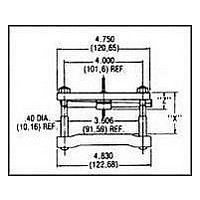
MECHANICAL DIMENSIONS
Power Disc Device
2.25 in. (57.2 mm)
3.50 in. (88.9 mm)
3.50 in. (88.9 mm)
4.00 in. (101.6 mm)
4.50 in. (114.3 mm)
5.25 in. (133.4 mm)
Dimensions: in. (mm)
Crossbar Stud Centerline
to Centerline Dimension
2.750 in. (69.9 mm) Ref
4.000 in. (101.6 mm) Ref
4.000 in. (101.6 mm) Ref
4.625 in. (117.5 mm) Ref
5.500 in. (139.7 mm) Ref
6.000 in. (152.4 mm) Ref
Normally stocked