109-1081 SANYO DENKI - SANACE FANS, 109-1081 Datasheet - Page 3
109-1081
Manufacturer Part Number
109-1081
Description
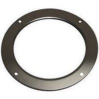
Inlet Nozzle
Manufacturer
SANYO DENKI - SANACE FANS
Datasheet
1.109-1081.pdf
(4 pages)
Specifications of 109-1081
Leaded Process Compatible
No
Peak Reflow Compatible (260 C)
No
Accessory Type
Inlet Nozzle
For Use With
Centrifugal Impellers - San Ace C150
Lead Free Status / RoHS Status
Lead free / RoHS Compliant


■
Output circuit : Open collector
■
■
PWM Input Signal Example
Output waveform ( Need pull-up resistor )
Connection Schematic
Specifications for Pulse Sensors
Input Signal Wave Form
DC fan input voltage
V
V
Inside of DC fan
V
V
In case of steady running
0V
OH
IH
IL
OL
PWM Input Signal
T
T
(
1
1
One revolution )
Isink
T
Sensor
T
Isource
2
○ +
○ +
○ −
○ −
T
0
T
Control
3
Pull-up resistor
Ic = 10mA MAX ( Rated Voltage 24V fan )
Ic = 10mA MAX ( Rated Voltage 48V fan )
T
4
Sensor output
Inside of DC fan
Rated Voltage 24V fan
V
Ic = 10mA MAX [ V
Rated Voltage 48V fan
V
Ic = 10mA MAX [ V
CE
CE
=+
=+
T
T
N = Fan speed ( min
1 ∼ 4
1 ∼ 4
30V MAX
60V MAX
≒ (
≒ (
V
V
PWM Duty Cycle ( % ) =
PWM Frequency 25 ( kHz ) =
Source Current ( Isource ) : 2mA Max. at control voltage 0V
Sink Current ( Isink ) : 1mA Max. at control voltage 5.25V
Control Terminal Voltage : 5.25V Max. (Open Circuit)
When the control lead wire is no connecting,
the speed is the same speed as at 100% of PWM cycle.
This fan speed should be controlled by PWM input signal
of either TTL input or open collector, drain input.
IH
IL
=0V to 0.4V
=4.75V to 5.25V
1/4 ) T
1/4 ) T
+
+
30V MAX ( Rated Voltage 24V fan )
60V MAX ( Rated Voltage 48V fan )
OL
OL
=
=
0
0
=
V
V
CE
CE
60/4N ( sec )
(
(
SAT ) = 0.6V MAX ]
SAT ) = 0.8V MAX ]
-1
)
T1
T × 100
1
T
φ
150
mm ×
35
mm
Related parts for 109-1081
Image
Part Number
Description
Manufacturer
Datasheet
Request
R

Part Number:
Description:
Inlet Nozzle
Manufacturer:
SANYO DENKI - SANACE FANS
Datasheet:

Part Number:
Description:
Inlet Nozzle
Manufacturer:
SANYO DENKI - SANACE FANS
Datasheet:
Part Number:
Description:
Inlet Nozzle
Manufacturer:
SANYO DENKI - SANACE FANS
Datasheet:

Part Number:
Description:
Plug & Cord Set For AC Fans
Manufacturer:
SANYO DENKI - SANACE FANS
Part Number:
Description:
Plug & Cord Set For AC Fans
Manufacturer:
SANYO DENKI - SANACE FANS
Part Number:
Description:
Plug & Cord Set For AC Fans
Manufacturer:
SANYO DENKI - SANACE FANS
Part Number:
Description:
Plug & Cord Set For AC Fans
Manufacturer:
SANYO DENKI - SANACE FANS
Part Number:
Description:
Plug & Cord Set For AC Fans
Manufacturer:
SANYO DENKI - SANACE FANS
Part Number:
Description:
Plug & Cord Set For AC Fans
Manufacturer:
SANYO DENKI - SANACE FANS
Part Number:
Description:
Plug & Cord Set For AC Fans
Manufacturer:
SANYO DENKI - SANACE FANS
Part Number:
Description:
Plug & Cord Set For AC Fans
Manufacturer:
SANYO DENKI - SANACE FANS

Part Number:
Description:
Finger Guard
Manufacturer:
SANYO DENKI - SANACE FANS
Datasheet: