TGP110 AIM-TTI INSTRUMENTS, TGP110 Datasheet
TGP110
Manufacturer Part Number
TGP110
Description
FUNCTION GENERATOR, PULSE, 10MHZ
Manufacturer
AIM-TTI INSTRUMENTS
Datasheet
1.TGP110.pdf
(1 pages)
Specifications of TGP110
Signal Generator Type
Pulse
Bandwidth
10MHz
Supply Voltage Range
197.8V To 262.2V
External Height
140mm
External Width
220mm
External Depth
230mm
Length/height, External
140mm
Lead Free Status / RoHS Status
na
An essential instrument
The generation of pulses for the stimulus and control of electronic systems
is beyond the capability of all but the most sophisticated of function gener-
ators.
The architecture of a dedicated pulse generator enables it to generate
pulses of a set width regardless of the repetition rate offering duty cycles
which can extend down to 1 in 100 million.
In addition to continuous operation, single or multiple pulses can be gener-
ated in response to trigger or gating signals with precisely defined timing
relationships.
A dedicated pulse-waveform output amplifier provides flat top pulses with
fast rise and fall times at variable amplitude.
Variable delay
The TGP110 offers selectable delay between the sync output and pulse
output. In triggered mode this also sets the delay between a trigger signal
and the start of the pulse.
Wide pulse range
The TGP110 can generate pulse widths in the range 50ns to 5s. There are
eight overlapping decade ranges with vernier control within each range.
The period range is 100ns to 10s, equivalent to a repetition rate range of
10MHz to 0.1Hz. Delay is independently adjustable over the same range
as pulse width.
A complement switch inverts the mark-space polarity.
Squarewave and double pulse
In square mode, squarewaves are generated at a frequency set by the pe-
riod controls alone. This provides a convenient means of generating vari-
able period edges where the pulse width is unimportant, for example.
In double pulse mode, a second pulse is generated within every period at a
set delay after the start of the first pulse. The delay is independently ad-
justable.
SPECIFICATIONS
PERIOD, PULSE WIDTH, DELAY
Each parameter is variable within 8 overlapping decade ranges with a vernier
providing continuously variable control within each range.
PERIOD
Range:
Jitter:
PULSE WIDTH
Range:
Jitter:
DELAY
Range:
Note: This is a faxable data sheet, a colour brochure is also available.
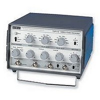
TGP110 10MHz Pulse Generator with Delay
0.1Hz to 10MHz frequency range
50ns minimum pulse width; fully variable pulse delay
Squarewave, double pulse and delayed pulse modes
Free-run, gated and triggered modes
50
Pulse
FUNCTION /MODE
Square
TRIGGER IN
output, variable 0.1V to 10V; TTL and sync outputs
Manual
Trigger
Run
Triggered
Gated
Double Pulse
Delayed
Pulse
THURLBY THANDAR INSTRUMENTS
100ns
10V Max.
1us
10us
100us
1
PERIOD
1ms
100nsec to 10sec (10MHz to 0·1Hz).
<0.1%.
50nsec to 5sec
<0.1%.
50nsec to 5sec
10ms
SYNC OUT
100ms
1s
10
500ns
Overlap
50ns
5US
1
PULSE WIDTH
50us
THURLBY THANDAR INSTRUMENTS
500us
5ms
10
TTL OUT
50ms
500ms
Overlap
500ns
50ns
1
Complement
5us
PULSE DELAY
Normal
50us
500us
10
5ms
50ms
500ms
MAIN OUT
50
3
4
2
5
1
AMPLITUDE
OPERATE
6
1V - 10V
0.1V - 1V
On
Off
7
10
8
9
TRIGGER, GATE
RUN
Normal operational mode in which pulses are generated continuously at
0.1Hz to 10MHz.
TRIGGERED
DC to 10MHz pulse train in synchronism with external trigger pulses; pulse
width determined by pulse width controls. Trigger can be generated manually
from front panel button.
GATED
0·1Hz to 10MHz pulse train, parameters set by period and pulse width con-
trols, starts synchronously with leading edge of gate input. Last pulse is com-
pleted at the end of gating period. Gating signal can be generated manually
from front panel button.
PULSE MODES
NORMAL PULSE
One pulse is generated each period. The delay setting is ignored.
SQUAREWAVE
0·1Hz to 10MHz squarewave, frequency set by the period controls. Pulse
width and delay settings ignored.
Mark : Space ratio:
DOUBLE PULSE
A second pulse is generated after a delay set by the delay controls; the delay
is related to the leading edge of the first pulse.
DELAYED PULSE
A pulse is generated after a delay set by the delay controls; the delay is re-
lated to rising edge of the trigger signal.
INPUTS
GATE/TRIG INPUT
Frequency range:
Signal range:
Min. pulse width:
Input Impedance:
OUTPUTS
50 OUTPUT
Amplitude:
Rise/Fall Times:
Aberrations:
AUX OUTPUT
Duplicates 50 output but at a fixed CMOS/TTL level.
SYNC OUTPUT
Amplitude:
Timing:
Duration:
COMPLEMENT SWITCH
Inverts the AUX and 50 outputs.
GENERAL
Power:
Size:
Weight:
Operating Range:
Storage Range:
Safety:
EMC:
Thurlby Thandar Instruments Ltd. operates a policy of continuous development and re-
serves the right to alter specifications without prior notice.
Designed and built in the EEC by:
e-mail: sales@ttinst.co.uk Web: http://www.ttinst.co.uk
Glebe Road, Huntingdon. Cambs. PE18 7DX England
Tel: +44 (0)1480 412451 Fax: +44 (0)1480 450409
Thurlby Thandar Instruments Ltd.
1:1 ±10%.
DC - 10MHz
TTL threshold; max. input ±10V.
>30nsec.
Typically 10k .
Two switch selectable ranges of 0·1V - 1·0V and
1V - 10V from 50 . (50mV to 500mV and 500mV to 5V
into 50 ). Adjustable within ranges by a single turn ver-
nier.
Typically 10nsec into 50 load. Maximum 15ns.
Typically <5% for output set at >20% of range maxi-
mum, into 50 .
A positive going pulse at CMOS/TTL level.
Leading edge starts >20nsec before the TTL/50 out-
put transition.
Typically 30nsec.
230V or 115V AC nominal 50/60Hz, adjustable internally;
operating range ±14% of nominal; 20VA max.
140 x 220 x 230mm (HxWxD)
1.6kg (3.5lb)
+ 5°C to 40°C, 20-80% RH.
- 40°C to 70°C
Complies with EN61010-1.
Complies with EN55081-1 and EN50082-1.