33250A AGILENT TECHNOLOGIES, 33250A Datasheet - Page 2
33250A
Manufacturer Part Number
33250A
Description
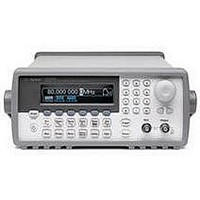
WAVEFORM GENERATOR ARB / FUNCTION, 80MHZ
Manufacturer
AGILENT TECHNOLOGIES
Datasheet
1.33250A.pdf
(4 pages)
Specifications of 33250A
Signal Generator Type
ARB/Frequency/Signal/DDS
Bandwidth
80MHz
Modulation Type
AM, FM, FSK
Supply Voltage Range
100V To 240V
External Height
104mm
External Width
254mm
Lead Free Status / RoHS Status
na


Waveforms
Standard
Arbitrary
Waveform length
Amplitude resolution 12 bits (including sign)
Repetition rate
Sample rate
Filter bandwidth
Non-vol. memory
Frequency Characteristics
Sine
Square
Pulse
Arb
Ramp
White noise
Resolution
Accuracy (1 year)
Sinewave Spectral Purity
Harmonic distortion
DC to 1 MHz
1 MHz to 5 MHz
5 MHz to 80 MHz
Total harmonic distortion
DC to 20 kHz
Spurious (non-harmonic)
DC to 1 MHz
1 MHz to 20 MHz
20 MHz 80 MHz
Phase noise (30 kHz band)
10 MHz
80 MHz
2
sine, square, pulse,
ramp, noise, sin(x)/x,
exponential rise,
exponential fall,
cardiac, DC volts
1 to 64K points
1 µHz to 25 MHz
200 MSa/s
50 MHz
Four (4) 64K wave-
forms
1 µHz to 80 MHz
1 µHz to 80 MHz
500 µHz to 50 MHz
1 µHz to 25 MHz
1 µHz to 1 MHz
50 MHz bandwidth
1 µHz;
except pulse, 5 digits
2 ppm, 18°C to 28°C
3 ppm, 0°C to 55°C
≤ 3 Vpp
-60 dBc
-57 dBc
-37 dBc
< 0.2% + 0.1 mVrms
-60 dBc
-50 dBc
-50 dBc + 6 dBc/oc-
tave
<-65 dBc (typical)
<-47 dBc (typical)
3
2
1
> 3 Vpp
-55 dBc
-45 dBc
-30 dBc
2
Signal Characteristics
Squarewave
Rise/Fall time
Overshoot
Asymmetry
Jitter (rms)
Duty cycle
Pulse
Period
Pulse width
Variable edge time
Overshoot
Jitter (rms)
Ramp
Linearity
Symmetry
Arb
Minimum edge time
Linearity
Settling time
Jitter (rms)
Output Characteristics
Amplitude (into 50Ω) 10 mVpp to 10 Vpp
Accuracy (at 1 kHz, >10 mVpp, Autorange on)
Flatness (sinewave relative to 1 kHz,
Autorange on)
Units
Resolution
Offset (into 50Ω)
Accuracy
Waveform Output
Impedance
Isolation
Protection
< 2 MHz
≥ 2 MHz
≤ 25 MHz
25 MHz to 50 MHz 40.0% to 60.0%
50 MHz to 80 MHz 50.0% (fixed)
< 10 MHz
10 MHz to 50 MHz ± 2% (0.2 dB)
50 MHz to 80 MHz ± 5% (0.4 dB)
< 8 ns
< 5%
1% of period + 1 ns
0.01% + 525 ps
0.1% + 75 ps
20.0% to 80.0%
20.00 ns to 2000.0 s
8.0 ns to 1999.9 s
5.00 ns to 1.00 ms
< 5%
100 ppm + 50 ps
< 0.1% of peak output
0.0% to 100.0%
< 10 ns
< 0.1% of peak output
< 50 ns to 0.5% of final
value
30 ppm + 2.5 ns
± 1% of setting ± 1
mVpp
± 1% (0.1 dB)
Vpp, Vrms, dBm,
high and low level
0.1 mV or 4 digits
± 5 Vpk ac + dc
1% of setting + 2 mV
+ 0.5% of amplitude
50Ω typical (fixed)
>10 MΩ (output dis-
abled)
42 Vpk maximum to
earth
short-circuit
protected
overload relay
automatically
disables main output
4
7
;
6
5
Modulation Characteristics
AM
Carrier waveforms
Mod. waveforms
Mod. frequency
Depth
Source
FM
Carrier waveforms
Mod. waveforms
Mod. frequency
Peak deviation
Source
FSK
Carrier waveforms
Mod. waveform
Internal rate
Frequency range
Source
External Modulation Input
Voltage range
Input impedance
Frequency
Latency
Burst
Waveforms
Frequency
Burst count
Start/Stop phase
Internal period
Gate source
Trigger source
Trigger delay
Sweep
Waveforms
Type
Direction
Start F/Stop F
Sweep time
Trigger
Marker
N-cycle, infinite
< 70 µs typical
sine, square, ramp, and
arb
sine, square, ramp,
noise, and arb
2 mHz to 20 kHz
0.0% to 120.0%
internal/external
sine, square, ramp, and
arb
sine, square, ramp,
noise, and arb
2 mHz to 20 kHz
DC to 80 MHz
internal/external
sine, square, ramp, and
arb
50% duty cycle square
2 mHz to 100 kHz
1 µHz to 80 MHz
internal/external
± 5 V full scale
10 Ω
DC to 20 kHz
sine, square, ramp,
pulse, arb, and noise
1 µHz to 80 MHz
1 to 1,000,000 cycles
or infinite
-360.0° to +360.0°
1 ms to 500 s
external trigger
single manual trigger,
internal, external trig
0.0 ns to 85.000 sec
sine, square, ramp, and
arb
linear and logarithmic
up or down
100 µHz to 80 MHz
1 ms to 500 s
single manual trigger,
internal, external trig
falling edge of sync
signal (programmable)
8