72-6825 CALIBRATED W/DATA TENMA, 72-6825 CALIBRATED W/DATA Datasheet
72-6825 CALIBRATED W/DATA
Specifications of 72-6825 CALIBRATED W/DATA


72-6825 CALIBRATED W/DATA Summary of contents
Page 1
... Oscilloscope Owner’s Manual ...
Page 2
USER MANUAL CONTENTS 1. PRODUCT INTRODUCTION................................................ 1-1.Description………………………………………………. 1-2.Feature…………………………………………………... 2. TECHNICAL SPECIFICATIONS………………………… PRECAUTIONS BEFORE OPERATION…….………….. 3-1.Unpacking the instrument………………….…………... 3-2.Checking the Line Voltage…………………..………….. 3-3.Environment……………………………………..……… 3-4.Equipment Installation and Operation……………….... 3-5.CRT Intensity…………………………………………… 3-6.Withstanding Voltage of Input Terminals……………... 4. PANEL INTRODUCTION……………………..………….. 4-1.Front Panel………………………………………………. ...
Page 3
USER MANUAL FOR UNITED KINGDOM ONLY NOTE: This lead/appliance must only be wired by competent persons WARNING: THIS APPLIANCE MUST BE EARTHED IMPORTANT: The wires in this lead are coloured in accordance with the following code: Green/ Yellow: Earth Blue: ...
Page 4
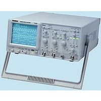
... USER MANUAL 1.PRODUCT INTRODUCTION 1-1. Description The 72-6825 is a 200MHz, two-channel, dual-sweep, portable oscilloscope for general purpose use. A microprocessor-based operating system controls most of the functions of the instrument, including cursor readout and digitized panel setting. On-screen alphanumeric readout and cursor function for voltage, time, frequency and phase measurement provide extraordinary operational convenience ...
Page 5
USER MANUAL 7) Trigger signal output The signal selected by the TRIGGER SOURCE is available. This output may be used to connect to a frequency counter or other instrument. 8) Panel setups lock To avoid unintentional touch of the setting, ...
Page 6
USER MANUAL 2.TECHNICAL SPECIFICATIONS Sensitivity 2mV~5V/DIV,11 step in 1-2-5 sequence Sensitivity Accuracy ±3% (5 DIV at the center display ) Continuously variable to 1/2.5 or less than Vernier Vertical Sensitivity panel-indicated value Frequency Bandwidth(-3dB 200MHz (2mV/DIV:DC ~ 20MHz) ...
Page 7
USER MANUAL 6-inch rectangular type with internal graticule Type 0%, 10%, 90% and 100% markers DIV (1 DIV = 1 cm) CRT Phosphor P31 Accelerating Potential 14.5kV approx. Illumination Continuous adjustable External intensity modulation Coupling DC Z-AXIS ...
Page 8
USER MANUAL 3.PRECAUTIONS BEFORE OPERATION 3-1.Unpacking the Oscilloscope The product has been fully inspected and tested before shipping from the factory. Upon receiving the instrument, please unpack and inspect it to check if there is any damages caused during transportation. ...
Page 9
... The front panel is subdivided into six sections: Display controls Vertical controls Horizontal controls Trigger controls Measurement and SAVE/RECALL controls Input connectors 10 USER MANUAL Front panel of 72-6825 11 ...
Page 10
USER MANUAL 4-1.Front Panel Display controls The display controls adjust the on-screen appearance of the waveform and provide a probe compensation signal source. (1).POWER – Pushbutton and symbols for ON(1) and OFF(0). When switch on the oscilloscope to have all ...
Page 11
USER MANUAL (7).20MHz BWL – Pushbutton with indicator LED. Briefly pressing the pushbutton, the bandwidth is reduced to approx. 20MHz, and the measurement is made by eliminating undesired high frequency signal from the waveform. Also the high frequency component over ...
Page 12
USER MANUAL (13)CH1 VOLTS/DIV. (14)CH2 VOLTS/DIV– Control knob for channel 1/channel 2 has double function. Turning the knob clockwise to increase the sensitivity in 1-2-5 sequence and turning it in the opposite direction (CCW) to decrease. The available range is ...
Page 13
USER MANUAL Horizontal controls: The horizontal controls select the time base operation mode and adjust the horizontal scale, position and magnification of the signal. (21)TIME/DIV– Control knob with double function. Turning the knob clockwise to reduce the deflection coefficient in ...
Page 14
USER MANUAL window segment decreases when the DELAY time coefficient is set to a lower value (higher time deflection speed). For better reading, the vertical position of the DELAY time base trace position can be shifted (please note TRACE SEP ...
Page 15
USER MANUAL Trigger controls The trigger controls determine the sweep start timing for both signal and dual trace operation. 22 USER MANUAL (26)MODE – Pushbutton and indicator LEDs. Pressing the pushbutton to select the trigger mode. The actual ...
Page 16
USER MANUAL (27)TRIGGER LEVEL/TV LINE SELECT—Control knobs TRIGGER LEVEL Turning the control knob causes a different trigger input setting (voltage), and set to a suitable position for the starting of triggered sweep of the waveform. An approximate trigger level setting ...
Page 17
USER MANUAL (29)SOURCE—Pushbutton and associated LEDs. Pressing the pushbutton to select the trigger signal source or the X signal for an X-Y operation. The actual setting is indicated in a LED and by the readout (“SOURCE”, slope, coupling). CH1 The ...
Page 18
USER MANUAL (31)TV-V/TV-H/TV-STD—Pushbutton for video sync signal selection. In the TV trigger mode, each time when the pushbutton of TV-V/TV-H/TV-STD is pressed, the video sync signal is displayed in the sequence as follows: TV-V—TV-H—TV-L(NTSC)—TV-L(PAL)—TV-L(SECAM)—TV-V TV-V Start the main trace at ...
Page 19
USER MANUAL (33)AUTOSET— Pressing briefly the AUTOSET pushbutton to set the instrument to the last time base mode of CH1, CH2 and DUAL. At the same time, the attenuators VOLTS/DIV are automatically set at a signal display height of approx. ...
Page 20
USER MANUAL FUNC(Function) In the AUTO measurement mode, each time when the pushbutton is briefly pressed the four measurement parameters will be selected in the sequence as follows: FREQ—PERIOD—±WIDTH—±DUTY—OFF In the CURSOR measurement mode, each time when the pushbutton is ...
Page 21
USER MANUAL (39)EXT—This BNC socket is the external trigger signal input. In dual X-Y mode, signals at this input are used for the X deflection. Pressing the TRIG. SOURCE (29) pushbutton until the information of “EXT, slope, coupling” is shown ...
Page 22
USER MANUAL 5. OPERATION METHOD This section contains basic operation information and techniques that should be considered before proceeding any measurement. As for the location and function of instrument controls, connectors, and indicators, refer to the “Instruction of Front Panel ...
Page 23
USER MANUAL 5-2.Connecting Input Signals Grounding The most reliable signal measurements are made when the oscilloscope and the unit under test are connected by a common reference (ground lead) in addition to the signal lead or probe. The ground lead ...
Page 24
USER MANUAL 7. Observe the displayed waveform and compare them with the waveforms shown in figure 5-2. If either probe needs to be adjusted, proceed the step 8. If either probe does not need to be adjusted, proceed the “Function ...
Page 25
USER MANUAL 4. Set both CH1 and CH2 COUPLING to GND. 5. Use the CH1 and CH2 POSITION controls to align both traces on the center graticule. 6. Open the CH2 INV by pressing and holding the pushbutton. 7. Set ...
Page 26
USER MANUAL Displaying the sum or difference of CH1 and CH2 To display the algebraic sum or difference of CH1 and CH2, proceed the following steps: 1.Set the ALT/CHOP/ADD button to ADD mode. The figure 5-6 below shows the sum ...
Page 27
USER MANUAL Setting up Dual X-Y Operation To use the oscilloscope in the dual X-Y mode, proceed the following steps: 1. Connect the horizontal or X-axis signal to the EXT (X) input. 2. Connect one of the vertical or Y-axis ...
Page 28
USER MANUAL Magnifying Waveform Events Use the ×10 MAG pushbutton to view small portions of a waveform as which is too far back from the starting point to view by using the TIME/DIV control. To use the ×10 MAG button, ...
Page 29
USER MANUAL TV-V/TV-H/TV-STD pushbutton to set TV-H triggering. To trigger the oscilloscope at the horizontal (signal TV-V/TV-H/TV-STD pushbutton to set TV-L triggering. The figure 5-12(a) shows vertical signal of TV-V and Figure 5-12(b) shows horizontal signal of TV-H and Fig. ...
Page 30
USER MANUAL 5-6.Measurement Application The oscilloscope has a cursor measurement system for making accurate, direct-readout voltage, time, frequency and phase measurements. The measurements described in this section are examples of typical applications using this measurement system. After becoming familiar with ...
Page 31
USER MANUAL 1. Set the VOLTS/DIV and VAR controls to provide an exact five-division vertical display. 2. Use the vertical POSITION control to control the negative amplitude of the signal on the 0% reference line and the positive amplitude on ...
Page 32
USER MANUAL AUTO MEASUREMENT Proceed a measurement by using the auto-measurement according to the following steps: 1. Pressing and holding the MEAS’MT FUNCTION pushbutton to turn on the auto-measurement and measurement readout. 2. Briefly pressing the pushbutton to select the ...
Page 33
USER MANUAL 6-3.Cleaning To clean the oscilloscope, use a soft cloth dampened in a solution of mild detergent and water. Do not spray cleaner directly onto the oscilloscope because it may leak into the cabinet and cause damage. Do not ...