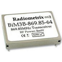
BIM3B-869.85-64 RADIOMETRIX, BIM3B-869.85-64 Datasheet - Page 3

BIM3B-869.85-64
Manufacturer Part Number
BIM3B-869.85-64
Description
TRANSCEIVER, 869.85MHZ
Manufacturer
RADIOMETRIX
Datasheet
1.BIM3B-869.85-64.pdf
(11 pages)
Specifications of BIM3B-869.85-64
Rohs Compliant
YES
RXD
Digital output from internal data slicer. The output is a squared version of the signal on pin 13 (AF) and
may be used to drive a decoder directly. The data is true data, i.e. as fed to the transmitter. Output is
“open-collector” format with internal 10k pullup to Vcc (pin 17).
AF
Buffered & filtered analogue output from FM demodulator. Standing DC bias of 1V approx. Useful for
test purposes or for driving external decoders. External load should be >10k
TXD
This DC-coupled transmitter modulation input will accept either serial digital data or high level linear
signals. Drive signal must be limited to 0V min, 3V max. See page 6 for suggested drive methods. Input
impedance >50k .
TX select
Active-low Transmit select. 47k internal pull-up to Vcc.
RX select
Active-low Receive select. 47k internal pull-up to Vcc.
* Loop-back allows the receiver to monitor the transmitted signal. Under these conditions the Tx
radiated signal level will be reduced to approximately -10dBm).
Vcc
DC +ve supply pin. +2.9 to +16.0 volts @ <17mA (@ 5mW). The supply should be clean, <20mV
Weight: 7g (typ.)
Radiometrix Ltd, BiM3B Data Sheet
Pin 15 TX
1
1
0
0
No pin
RF GND
Antenna
RF GND
0V
Pin 16 RX
1
0
1
0
pin 12
pin 13
pin 14
pin 15
pin 16
pin 17
1
2
3
4
5
6
7
8
9
side view (through can)
top view (without can)
Function
Power down (<10 A)
Receiver enabled
Transmitter enabled
Self test loop-back*
Fig. 3: Physical dimensions
30.48 mm
33 mm
18
17
16
15
14
13
12
11
10
recommended PCB hole size: 1.2 mm
module footprint size: 25 x 32 mm
pin pitch: 2.54 mm (0.1")
pins 4, 5, 6, 7
5 mm
TX SELECT
0V
Vcc
RX SELECT
TXD
AF
RXD
RSSI/CD
0V
side view (with can)
& 8
23 mm
// <100pF
are not fitted
P-P
ripple.
page 3


