RCU04 LPRS, RCU04 Datasheet - Page 2
RCU04
Manufacturer Part Number
RCU04
Description
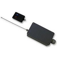
REMOTE SWITCHING UNIT, IP65, MAINS
Manufacturer
LPRS
Datasheet
1.RCU04.pdf
(5 pages)
Specifications of RCU04
External Depth
65mm
External Length / Height
40mm
External Width
115mm
Ip/nema Rating
IP65
Supply Voltage Max
240VAC
Supply Voltage Min
220VAC
Lead Free Status / RoHS Status
Lead free / RoHS Compliant


Lyon Road, Atlantic Street Broadheath, Altrincham, Cheshire. WA14 5DG
Tel: 0161-929-7550 Fax 0161-929-7551
E-mail sales@rustelectronics.co.uk
www.rustelectronics.co.uk
MAINS REMOTE SWITCHING UNIT RCU-O4
The RCU-O4 is a radio remote controlled switching unit that will allow the remote operation of any appropriate electrical
appliance that is required. The unit is constructed to industrial/commercial standards, giving the convenience of remote
operation and in most cases the reduction in installation costs will exceed the cost of switching unit.
The output of the unit is in the form of a relay change over contact rated at 8 amps 240V AC.
On the reception of a valid signal the output can be programmed to be momentary, toggled or timed using the internal dip
switches.
The remote control is achieved by using an encoded UHF radio signal produced by a key fob transmitter with a super-hetrodyne
receiver validating the transmitted code and activating the output accordingly.
The receiver unit is IP65 rated (see INSTALLATION) allowing external positioning, with a self- contained power supply.
The electrical appliance can be operated remotely be simply connecting to a mains supply via the RCU-O4 remote receiver unit.
INSTALLATION
First remove the lid and carefully retain the 4 lid screws.
The DIP switches should be positioned in line with the table (overleaf), in order to establish the correct output control (Latched,
momentary or timed).
The receiver unit must be securely mounted, using the mounting holes provided, vertically with the aerial pointing upwards.
Avoid positioning in close proximity to electronic equipment as interference from such equipment in certain circumstances could
reduce the operational range.
The wiring must be passed through the sealing gland, and connected appropriately (see diagram). Ensure that the supply to the
unit is appropriately fused and if there is any doubt whatsoever regarding the electrical installation consult a competent
qualified electrician. The cables must be clamped securely by tightening the sealing gland using a 19mm spanner ensuring that
an adequate seal is formed against the outer sleeving of the cables (IP65 weather proof).
All connections to the unit must made via the screw blocks provided. Ensure that there are no loose strands of wire present and
that all connections are secure. If the load requires an earth, this MUST be provided, the comm block can be used to connect
the incoming earth to corresponding earth on the load.
Refer to 'Wiring diagram' for connection details.
See 'Typical application' of a load connected to a mains supply.
Prior to attaching the lid, check the integrity of the sealing gasket, using all 4 screws provided, tighten evenly until a
weatherproof seal can be established.
Before applying power ensure that the installation is both complete and safe.
After the power is applied allow approximately 5 seconds for the electronics to stabilise. Activation of the remote transmitter will
activate the receiver output, provided that it is within range.
Mains Remote Switching Unit RCU-04
2
Related parts for RCU04
Image
Part Number
Description
Manufacturer
Datasheet
Request
R

Part Number:
Description:
ANTENNA, FLEXIBLE, UNIVERSAL, 2.4G
Manufacturer:
LPRS
Datasheet:

Part Number:
Description:
ANTENNA, WHIP, 433MHZ, R/A
Manufacturer:
LPRS
Datasheet:

Part Number:
Description:
ANTENNA, WHIP, 433MHZ
Manufacturer:
LPRS
Datasheet:

Part Number:
Description:
ANTENNA, WHIP, R/A, 800-900MHZ
Manufacturer:
LPRS
Datasheet:

Part Number:
Description:
ANTENNA, WHIP, 800-900MHZ
Manufacturer:
LPRS
Datasheet:
