FM-TX1-433A RF Solutions, FM-TX1-433A Datasheet - Page 2
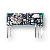
FM-TX1-433A
Manufacturer Part Number
FM-TX1-433A
Description
MODULE, TRANSMITTER, FM
Manufacturer
RF Solutions
Datasheet
1.FM-TX1-433A.pdf
(6 pages)
Specifications of FM-TX1-433A
Svhc
No SVHC (15-Dec-2010)
Current Rating
14A
Data Rate Max
10000bps
Frequency
433MHz
Operating Distance
200m
Operating Temperature Max
55°C
Operating Temperature Min
-10°C
Safety Category
DTI MPT1340


D
D
S
S
0
0
0
0
0
0
0
0
Data in can accept data in either digital or direct analogue form (AFSK). The input frequency bandwidth
ranges from DC to 10KHz; however, it is not possible to pass data with a DC component because of
frequency errors and drifts between the transmitter and receiver. The frequency differences between
transmitter and receiver will produce a DC offset error which will result in the receiver module producing errors
on long high or low pulses which exceed the maximum pulse width specification (please refer to the Receiver
data sheet, RF Solutions Doc FMRX1-XXX).
Data in should be driven from a CMOS logic output. The power supply for the CMOS circuit should be the
same as that for the transmitter.
Analogue drive (e.g. two tone FSK) is possible; however the peak to peak level must be in the range 5 to 9V,
and never fall below 0V. Please note that there may be some 2nd harmonic distortion due to the varactor
modulator (typically <15%). This can be reduced somewhat by predistorting the analogue waveform.
This range of Radio transmitters is approved by the Department of Trade & Industry (D.T.I. Specification
MPT1340) in the U.K., and therefore the user requires no radio operating licence in the U.K.
Please note however the following requirements to comply with MPT1340;
2
2
OPERATIONAL DESCRIPTION
LICENCE EXEMPTION
ANTENNA DESIGN
The range achieved from the system is dependant on the choice and position of the antenna. The space
around the antenna is as important as the antenna itself. The optimum position is to locate the antenna so
that is protrudes directly out the top of the transmitter box. If this is not possible due to other design
constraints, try to keep the antenna away from other metal in the system such as transformers, batteries
and PCB tracks, especially ground planes. In particular, the ‘HOT’ end of the antenna should be kept as far
away as possible from these.
For further information on Antenna design please see our full product catalogue which gives recommended
applications guidance.
PIN ASSIGNMENTS
0
0
PIN No
R
R
1
2
3
4
5
e
e
1. All transmitters shall use integral antennas only. Receivers may use an external or integral
2. The equipment in which the module is used must carry an inspection mark located on the outside
v
v
2
2
antenna. An integral antenna is defined as one which is designed to be connected permanently to
the transmitter or receiver without the use of an external feeder.
of the equipment which is clearly visible. It shall state “MPT1340 W.T. Exempt”. The minimum
dimensions of the mark shall be 10 x 15mm and the figure height shall be not less than 2mm.
.
.
1
1
J
J
R.F. GND
R.F. OUT
DATA IN
u
u
l
l
NAME
y
y
Vcc
Vss
‘
‘
9
9
9
9
F
F
M
M
Ground Plane.
The Antenna radiates against this (Internally connected to pin 4)
Connect to Antenna (Output Impedance = 50 )
Supply Voltage
0 Volt Supply
Input pin. Should be driven by CMOS Drive with same supply as pin 3
T
T
R
R
A
A
N
N
S
S
1
1
9
9
M
M
9
9
9
9
I
(Internally connected to pin 1)
I
T
T
R
R
E
E
T
T
G
G
E
E
N
N
o
o
R
R
2
2
7
7
7
7
M
M
4
4
0
0
0
0
O
O
1
1
DESCRIPTION
,
,
D
D
E
E
N
N
U
G
G
U
L
L
L
L
A
A
N
N
E
E
D
D
.
.
S
S
.
.
F
F
M
M
T
T
X
X
P
P
1
a
1
a
g
g
-
-
e
e
2
2
X
X
X
X
X
X
X
X
Related parts for FM-TX1-433A
Image
Part Number
Description
Manufacturer
Datasheet
Request
R

Part Number:
Description:
FM/AM Radio
Manufacturer:
UTC [Unisonic Technologies]
Datasheet:

Part Number:
Description:
IC DECODER STEREO PLL 8SOIC
Manufacturer:
ST-Ericsson Inc
Datasheet:
Part Number:
Description:
IC FM RADIO CIRCUIT 16SOIC
Manufacturer:
ST-Ericsson Inc
Datasheet:

Part Number:
Description:
IC FM IF SYSTEM LOW PWR 16-SOIC
Manufacturer:
NXP Semiconductors
Datasheet:

Part Number:
Description:
IC ENCODER TRANSMITTER RF 8DIP
Manufacturer:
RF Solutions
Datasheet:

Part Number:
Description:
IC DECODER RECEIVER RF 18DIP
Manufacturer:
RF Solutions
Datasheet:

Part Number:
Description:
IC ENCODER 3 DGTL I/O SOT23-6
Manufacturer:
RF Solutions
Datasheet:

Part Number:
Description:
IC ENCODER 3 DGTL I/O 8-PDIP
Manufacturer:
RF Solutions
Datasheet:

Part Number:
Description:
IC DECODER 3 DGTL I/O 8-PDIP
Manufacturer:
RF Solutions
Datasheet:

Part Number:
Description:
IC DECODER 3 DGTL I/O 8-SOIC
Manufacturer:
RF Solutions
Datasheet:
Part Number:
Description:
118 SERIES AM REMOTE CONTROL SYSTEMS.
Manufacturer:
RF Solutions Ltd.