ER400TRS EASY RADIO, ER400TRS Datasheet - Page 9
ER400TRS
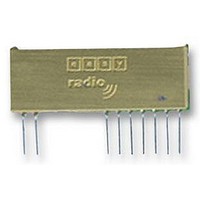
Manufacturer Part Number
ER400TRS
Description
MODULE, TX, 433MHZ
Manufacturer
EASY RADIO
Datasheet
1.ER400TRS.pdf
(30 pages)
Specifications of ER400TRS
External Depth
4mm
External Length / Height
14mm
External Width
37mm
Frequency
433.92MHz
Operating Temperature Max
65°C
Operating Temperature Min
-20°C
Output Power
10mW
Rf Sensitivity
-100dBm
Range
250m


Application & Operation ERx00TS-02 & RS-02
Figure 5 shows a typical system block diagram comprising hosts (user’s application) connected to Easy-
Radio Transmitters and Receivers. Host (A) will be monitoring (collecting data) and Host (B) will be receiving
and processing this data.
The Host (A) should provide the serial data input (up to a maximum 180 characters per packet) to the Easy-
Radio transmitter. The data should be sent in ‘bursts’ therefore allowing adequate time for transmission and
reception over the RF link (See Figure 6). The receiver, upon reception and decoding of the RF transmission
immediately sends serial data to the Host B.
Data is sent and received in standard ‘RS232’ serial format (logic level only) and there is no restriction on the
characters that may be sent. (HEX 00 – FF)
There is no ‘RF handshaking’ provided at either the transmitter or receiver. The user should therefore ensure
that sufficient time is allowed for the completion of transmission and reception of data. The Timing
Specifications detail these requirements (see page 9). Transmitter Host (A) must allow time for the ‘Over Air’
transmission and for the receiving Host (B) to unload (and process) the data before sending any more new
data. The receiver Host (B) must always be ‘ready and waiting’ for data to arrive. It should be possible to use
fast response ‘interrupts’ without any loss of data.
With such a ‘one-way’ (simplex) system there is no confirmation of the satisfactory reception of the data and
for added reliability it is recommended that the data be sent, perhaps, repetitively several times. For
increased reliability the use of transceivers (which can acknowledge packet reception) is recommended.
Easy-Radio services do not provide automatic acknowledgement (or re-tries) but these can be provided by
the users application.
LPRS Data Sheet
ERx00-02 Series V2.3
A. Host (A) sends serial data to the Easy-Radio Transmitter (A). The data must be continuously
B. After detecting either the ‘End of Data’ gap or the ‘Buffer Full’ condition the controller enables RF
C. After checking the data for integrity, the Data within the receive buffer of Easy-Radio Receiver (B) is
A
B
C
streamed at the selected baud rate and it loads an internal transmit buffer until either it is full or a
gap of two bytes is detected.
transmit and sends the data in the buffer using Manchester coding for efficient transmission across
the RF link. Any Easy-Radio receivers within range that ‘hear’ the transmission will simultaneously
decode the data and place it into their receive buffers.
then sent continuously to the host at the selected baud rate.
Host
(A)
Datasheet Revision 2.3 Sept 2005
Transmit Data (TXD)
Two Byte Delay for 'End of Data'
ER400TS Transmitter, ER400RS Receiver & ER400TRS Transceiver
ER900TS Transmitter, ER900RS Receiver & ER900TRS Transceiver
Figure 5 Typical System Block Diagram
Easy-Radio
Transmitter
Figure 6 Serial Data
Easy-Radio ‘02’ (2
RF Link
Host (A) sends serial data to Easy-Radio (A)
Easy-Radio (A) Encodes data then Transmits
Over Air
Easy-Radio (B) Receives & Decodes
Easy-Radio (B) sends serial data to Host (B)
Copyright LPRS 2005.
nd
Easy-Radio
Receiver
Generation Modules)
Receive Data Output
Host
(B)
Page 9 of 30
Related parts for ER400TRS
Image
Part Number
Description
Manufacturer
Datasheet
Request
R

Part Number:
Description:
EVALUATION KIT, EASY RADIO
Manufacturer:
EASY RADIO
Datasheet:

Part Number:
Description:
MODULE, RECEIVER, EASY RADIO
Manufacturer:
EASY RADIO
Datasheet:

Part Number:
Description:
TRANSMITTER, EASY RADIO, 2BUTTON, 434MHZ
Manufacturer:
EASY RADIO
Datasheet:

Part Number:
Description:
MODULE, RX, FM, 433MHZ
Manufacturer:
EASY RADIO
Datasheet:
