200-433FR1 RF Solutions, 200-433FR1 Datasheet - Page 8
200-433FR1
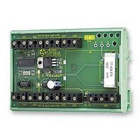
Manufacturer Part Number
200-433FR1
Description
TRANSMITTER, ENCODER, 8I/P
Manufacturer
RF Solutions
Datasheet
1.200-433FR1.pdf
(14 pages)
Specifications of 200-433FR1
Svhc
No SVHC (15-Dec-2010)
Frequency
433.92MHz
Range
200 M


DS200-2 Jul ‘02
Note: It is not possible erase individual transmitters.
When the system is configured with 204 Transmitter encoders these outputs can provide variable timed
outputs controlled by VR1-3 with an adjustable delay of from zero to 15 minutes.
1. Remove power.
2. Place a shorting link header on J8.
3. Apply power and the output LEDs will operate alternately 1 –16 and then repeat.
4. Depress and release the learn button twice.
5. The 210Rx will then enter the time set mode where the timing pots for channels 1, 2 and 3 can be
6. Using a fine screwdriver, adjust potentiometer VR1 for OP1, VR2 for OP2 and VR3 for OP3 .
7. When setting VR1-3, LED’s 9-15 give an indication of the % of time delay set (as a bargraph
Before learning check the following on the 200Tx
1. On the 200Tx, configure the OPT3 ‘8/15’ link. This link maps the 200Tx inputs to the 210Rx outputs. 1-8
2. On the 200Tx unit, remove the Link header ‘OPT1‘ (auto Tx). (This prevents automatic transmission during
3. On the 200Tx unit, place an enable link on any one of the enable link positions.
4. Briefly press the 210Rx Learn Switch: Note that the 210Rx Learn LED will flash.
5. Wait for the 210Rx LED to stop flashing.
Erasing the 210Rx Receiver Decoder’s Memory
1. To completely erase the 210Rx decoder’s memory, press and hold the 210Rx learn switch. The learn LED
2. After a period of 10 seconds the learn LED will turn off. Release the learn button and all the output LEDs
Configuration of the Outputs
Links J1-16 configure the operation of the outputs according to the table below. Note that the link status is
read only on power up and thus after changing the links, power must be removed and re-applied for the new
status to be identified.
Timed Outputs (O/P1-3)
Setting the Timed outputs on O/P1-3 (for use with a 204Tx only).
Operating the 210Rx with a ‘200 series’ Transmitter
Each 210Rx can learn up to 48, 200Tx encoders and during the learn process the receiver learns the
encoder’s unique identity code
which must be fitted for that input to operate.
To learn a new 200Tx encoder follow this procedure;
Connected
will illuminate when the switch is first pressed
will now flash alternately to indicate that all encoder data has been erased.
set. Initially LED1 will illuminate. This is to indicate that output 1 timer is to be set. Pressing the learn
switch will allow the user to cycle through the three timed outputs. The illuminated LED (1,2 or 3)
indicates which channel is being set up.
display). If no time delay is required then set all LED’s off. For maximum delay set all 7 LED's (9-15)
to on.
with link removed, or 9-15 with link in place.
the learn process).
J1 – 16
Open
Latch or Timed
Mom or Timed
O/P 1 – 3
‘DIN R
.
Each Transmitter/encoder input has an associated ‘enable’ option link
AIL
©2002 Reg. No. 227 4001, England
Mom (The relay operates for as long as the transmitter switch is held on)
Latch (The relay operates until the Transmitter is operated again)
’ R
ADIO
R
EMOTE
O/P 4 -16
C
ONTROL
Page 8
Related parts for 200-433FR1
Image
Part Number
Description
Manufacturer
Datasheet
Request
R

Part Number:
Description:
200/400MMAC 16-bit DSP MICROCOMPUTER
Manufacturer:
Analog Devices Inc
Datasheet:

Part Number:
Description:
200 W LDMOS avionics power transistor for transmitter applications at frequencies from 1030 MHz to 1090 MHz
Manufacturer:
NXP Semiconductors
Datasheet:
Part Number:
Description:
200 W LDMOS power transistor for base station applications at frequencies from 1450 MHz to 1550 MHz
Manufacturer:
NXP Semiconductors
Datasheet:

Part Number:
Description:
200 W LDMOS power transistor for base station applications at frequencies from 2110 MHz to 2170 MHz
Manufacturer:
NXP Semiconductors
Datasheet:
Part Number:
Description:
200 W LDMOS power transistor for base station applications at frequencies from 2110 MHz to 2170 MHz
Manufacturer:
NXP Semiconductors
Datasheet:

Part Number:
Description:
IC ENCODER TRANSMITTER RF 8DIP
Manufacturer:
RF Solutions
Datasheet:

Part Number:
Description:
IC DECODER RECEIVER RF 18DIP
Manufacturer:
RF Solutions
Datasheet:

Part Number:
Description:
IC ENCODER 3 DGTL I/O SOT23-6
Manufacturer:
RF Solutions
Datasheet:

Part Number:
Description:
IC ENCODER 3 DGTL I/O 8-PDIP
Manufacturer:
RF Solutions
Datasheet:

Part Number:
Description:
IC DECODER 3 DGTL I/O 8-PDIP
Manufacturer:
RF Solutions
Datasheet:

Part Number:
Description:
IC DECODER 3 DGTL I/O 8-SOIC
Manufacturer:
RF Solutions
Datasheet:

Part Number:
Description:
118 SERIES AM REMOTE CONTROL SYSTEMS.
Manufacturer:
RF Solutions Ltd.