CDPRX03BS-R 434 LPRS, CDPRX03BS-R 434 Datasheet - Page 5
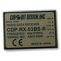
CDPRX03BS-R 434
Manufacturer Part Number
CDPRX03BS-R 434
Description
RECEIVER, NARROW BAND, 434MHZ
Manufacturer
LPRS
Datasheet
1.CDPRX03BS-R_434.pdf
(10 pages)
Specifications of CDPRX03BS-R 434
Current Rating
24mA
Data Rate
4800 Bps
Data Rate Max
4800bps
External Depth
8mm
External Length / Height
26mm
External Width
36mm
Frequency
434.075MHz
Operating Temperature Max
55°C
Operating
RoHS Compliant


CDP-RX-03AS UHF Radio Data Module Operation Guide
filter and comparator. For simple FSK modulation of digital data, the DATA out terminal can
be used. The signal can be easily connected to other digital circuits.
The AF and DATA output will show noise on the output when no signal is received. Valid data
signals can be detected by utilizing the RSSI output.
The third output is called RSSI. It is an indicator of the received signal strength. It can be used
to drive an external mute circuit.
Control terminal can be used to control Vcc supply for internal circuit.
Antennas:
Most important for effective data transmission is selection of a good antenna, and RF
grounding, both for the transmitter and the receiver. Without an antenna it is impossible to
transmit data over a long distance range.
The receiver has a simple antenna input pin. Any suitable UHF antenna can be connected to it.
The easiest way to connect an antenna to the CDP-RX-03AS is to solder an 8.6cm (868MHz)
or 17.3cm (434MHz) wire directly to the antenna input. If the receiving antenna is installed
away from the receiver module, a 50-Ohm Coax antenna wire can be used. The shielding of
the antenna wire should be soldered to the case near the antenna input of the CDP-RX-03AS.
It is possible, but not recommended to connect the receiver module and the antenna by a
connection on a PCB. This will decrease the receiver performance in most cases.
In most cases the following basic rules will help you.
The receiver has no internal mute circuit to avoid delays and achieve maximum sensitivity.
• Connect an antenna with 50-Ohm impedance.
• Lambda/4 whip antenna length is approximately 17.3cm for 434MHz and 8.6cm for
• Place the antenna vertically, straight up or down from the transmitter and receiver module.
• Do not cover the antenna with metal parts.
• The connection of the metal surface of the transmitter case to a larger metal part (ground
• The human body can have similar effects like metal objects. Pocket transmitters should be
• Best range is achieved if the transmitter and receiver antenna have a direct visual
• The transmission is influenced by reflections of the transmitter signal on metallic surfaces
868Mhz.
plane) will increase radiation efficiency. Such metal part should not be placed near the
antenna.
taken in the hand and put in a position away from the body and pointed in the direction of
the receiver.
connection. Any object in between the transmitter and receiver antenna, and metallic
objects in particular, will decrease the range.
and building. There is possibility to have data error by overlaying the direct and reflected
signal.
CIRCUIT DESIGN, INC.
5
Related parts for CDPRX03BS-R 434
Image
Part Number
Description
Manufacturer
Datasheet
Request
R

Part Number:
Description:
ANTENNA, FLEXIBLE, UNIVERSAL, 2.4G
Manufacturer:
LPRS
Datasheet:

Part Number:
Description:
ANTENNA, WHIP, 433MHZ, R/A
Manufacturer:
LPRS
Datasheet:

Part Number:
Description:
ANTENNA, WHIP, 433MHZ
Manufacturer:
LPRS
Datasheet:

Part Number:
Description:
ANTENNA, WHIP, R/A, 800-900MHZ
Manufacturer:
LPRS
Datasheet:

Part Number:
Description:
ANTENNA, WHIP, 800-900MHZ
Manufacturer:
LPRS
Datasheet: