HAAV4-27 IDEC, HAAV4-27 Datasheet - Page 6
HAAV4-27
Manufacturer Part Number
HAAV4-27
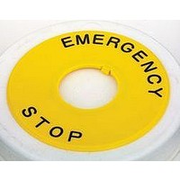
Description
NAMEPLATE, WARNING, 60MM DIA
Manufacturer
IDEC
Datasheet
1.HAAV4-27.pdf
(6 pages)
Specifications of HAAV4-27
Label Type
Warning
Label Size
60mm Dia
Background Color
Yellow
Legend
Emergency Stop
Color
Yellow
For Use With
XA Series Emergency Stop Switches
Lead Free Status / RoHS Status
Lead free / RoHS Compliant


10
IDEC Traditional E-Stops and Accessories
HW 22mm E-Stops
E-Stop Accessories
HW 22mm Pushlock Turn Reset
40mm Mushroom
Contacts
1NO
1NC
1NO-1NC
2NC
HW 22mm Push-Pull 40mm Mushroom
Contacts
1NO
1NC
1NO-1NC
2NC
HW 22mm Pushlock Turn Reset
40mm Yellow Mushroom*
Contacts
1NO
1NC
1NO-1NC
2NC
* Yellow button should not be used as an emergency stop switch
B
A
Plastic Bezel
HW1B-V4F10-R
HW1B-V4F01-R
HW1B-V4F11-R
HW1B-V4F02-R
Plastic Bezel
HW1B-Y2F10-R
HW1B-Y2F01-R
HW1B-Y2F11-R
HW1B-Y2F02-R
Plastic Bezel
HW1B-V4F10-Y
HW1B-V4F01-Y
HW1B-V4F11-Y
HW1B-V4F02-Y
E-Stop Shrouds
E-Stop Nameplates
A
B
22mm “Emergency Stop”
16mm “Emergency Stop”
22mm “Emergency Stop”
HW9Z-KG1-TK2120
HW9Z-KG2-TK2120
16mm Blank
22mm Blank
Jumbo Mushroom
Part Number
Size and Style
Metal Bezel
HW4B-Y2F10-R
HW4B-Y2F01-R
HW4B-Y2F11-R
HW4B-Y2F02-R
Metal Bezel
HW4B-V4F10-R
HW4B-V4F01-R
HW4B-V4F11-R
HW4B-V4F02-R
Metal Bezel
HW4B-V4F10-Y
HW4B-V4F01-Y
HW4B-V4F11-Y
HW4B-V4F02-Y
Ø
Ø
60mm
60mm
Ø
80mm For
Ø
Ø
60mm
60mm
Part Number
HWAV5-27
48.0
HAAV4-27
64.0
HWAV-27
HAAV4-0
HWAV-0
22.0
16mm
16mm
22mm
22mm
22mm
HW 22mm Pushlock Key Reset
40mm Mushroom
Contacts
1NO
1NC
1NO-1NC
2NC
HW 22mm EMO Pushlock Turn Reset
40mm Mushroom
Contacts
1NO
1NC
1NO-1NC
2NC
HW 22mm Pushlock Turn Reset
60mm Jumbo Mushroom
Contacts
1NO
1NC
1NO-1NC
2NC
38.0
ID
Gasket
60mm
60mm
60mm
60mm
80mm
OD
Plastic Bezel
HW1B-X4F10-R
HW1B-X4F01-R
HW1B-X4F11-R
HW1B-X4F02-R
Plastic Bezel
HW1B-V4F10-R-EMO-2
HW1B-V4F01-R-EMO-2
HW1B-V4F11-R-EMO-2
HW1B-V4F02-R-EMO-2
Plastic Bezel
HW1B-V5F10-R
HW1B-V5F01-R
HW1B-V5F11-R
HW1B-V5F02-R
Metal Bezel
HW4B-X4F10-R
HW4B-X4F01-R
HW4B-X4F11-R
HW4B-X4F02-R
Metal Bezel
HW4B-V4F10-R-EMO-2
HW4B-V4F01-R-EMO-2
HW4B-V4F11-R-EMO-2
HW4B-V4F02-R-EMO-2
36.5
XA & XW Technical Information
Connection Diagrams and Panel Cutouts
Left
Left
Conforming to Standards
Standard Operating Condition
Operating Force
Minimum Force to Latch
Maximum Travel to Latch
Maximum Travel
Shock Resistance
Vibration Resistance
Life
Degree of Protection
Short-Circuit Protection
Terminal Shape
Applicable Wire Size
Soldering
Recommended Terminal Torque
Weight (Approx.)
X1
4NC
1
2
1
2
TOP
TOP
LED
2
1
Specifi cations
2
1
X2
Right
Right
Left
Left
1NO-3NC
X1
1
4
1
4
TOP
TOP
LED
2
3
2
3
X2
IEC60947-5-1, EN60947-5-1, IEC60947-5-5, EN60947-5-5, JIS C8201-5-1, UL508, CSA C22.2 No.14
Operating Temperature:
Non-illuminated -25 to +60
Illuminated -25 to +55
Operating Humidity: 45 to 85%RH Without Condensing
Storage Temperature: 45 to +80
Pushlock: 10.5N
Pull Reset: 10N
Turn Reset: 0.16N-m
60N
4.0mm
4.5mm
Operating Extremes: 150m/s
Damage Limits: 1000m/s
10 to 500Hz, Amplitude 0.35mm
Acceleration 50m/s
10 to 500Hz, Amplitude 0.35mm
Acceleration 50m/s
Mechanical: 250,000 Minimum
Electrical: 100,000 Minimum
250,000 or more (24V AC/DC 100mA)
IP65 (IEC60529)
250V/10A Fuse (Type aM IEC60269-1/IEC60269-2)
Solder Terminal
PCB Terminal
Solder/PCB Terminal: 1.25mm
(AWG 16 Maximum)
20W/5sec Maximum
260ºc/3sec Maximum
40mm Button: 28 grams
Right
Right
Left
Left
X1
2NC
3
4
3
4
TOP
TOP
LED
2
2
4
3
4
3
(5G)
(5G)
˚
C Without Freezing
X2
2
(100 G)
Right
Right
˚
XA
C Without Freezing
—
2
���������������
(15G)
2
�������������
Maximum
˚
C
Left
����
Left
���
1NO-1NC
X1
���
1
4
3
4
TOP
TOP
LED
2
3
4
3
X2
Right
Right
50mm
�
Pushlock: 32N
Pull Reset: 21N
Turn Reset: 0.27N-m
80N
M3 Screw Terminal
Screw Terminal: 0.75 to 1.25mm
(AWG 18 to 16)
0.6 to 1.0N-m
40mm Button: 72 grams
60mm Button: 81 grams
�����
�������������
50mm
XA
����
�
�
���
����
0
Y
XW
––
ø22.3
XW
+0.4
0
X
2
������������
For Standard XW
X=Y=50mm
For Jumbo XW
X=Y=70mm
11
Related parts for HAAV4-27
Image
Part Number
Description
Manufacturer
Datasheet
Request
R

Part Number:
Description:
Cable; Between IDEC MicroSmart (port 1 or 2) and HG2F/3F/4F; 5 ft.
Manufacturer:
IDEC Corporation
Datasheet:
Part Number:
Description:
Cable; Between IDEC Micro^3C/ONC/MicroSmart (port 2) PLCs and HG2F/3F/4F; 5 ft.
Manufacturer:
IDEC Corporation
Datasheet:
Part Number:
Description:
Angled Key for Idec HS6B Safety Switch
Manufacturer:
IDEC Corporation
Datasheet:
Part Number:
Description:
Accessory, L-Shaped Key for Idec HS5B and HS5E Safety Switch
Manufacturer:
IDEC Corporation
Datasheet:
Part Number:
Description:
Accessory, Straight Key for Idec HS5B and HS5E Safety Switch
Manufacturer:
IDEC Corporation
Datasheet:
Part Number:
Description:
INDICATOR INCANDESCENT LAMP, GREEN
Manufacturer:
IDEC
Datasheet:

Part Number:
Description:
LAMP, INDICATOR, INCAND, AMB
Manufacturer:
IDEC
Datasheet:
Part Number:
Description:
LAMP, INDICATOR, INCAND, GRN
Manufacturer:
IDEC
Datasheet:
Part Number:
Description:
LAMP, INDICATOR, INCAND, GRN
Manufacturer:
IDEC
Datasheet:
Part Number:
Description:
LAMP, INDICATOR, INCANDESCENT, RED
Manufacturer:
IDEC
Datasheet:
Part Number:
Description:
LAMP, INDICATOR, INCANDESCENT, RED
Manufacturer:
IDEC
Datasheet:
Part Number:
Description:
LAMP, INDICATOR, INCAND, BLU
Manufacturer:
IDEC
Datasheet:

Part Number:
Description:
LAMP, INDICATOR, INCAND, 40MM, GRN
Manufacturer:
IDEC
Datasheet:
Part Number:
Description:
LAMP, INDICATOR, INCAND, MINI, BLUE
Manufacturer:
IDEC
Datasheet:

Part Number:
Description:
PILOT, LIGHT, OPERATOR
Manufacturer:
IDEC
Datasheet: