ID30C8 TELEX COMMUNICATIONS, ID30C8 Datasheet - Page 2
ID30C8
Manufacturer Part Number
ID30C8
Description
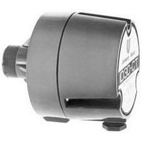
Drivers For Public Address Horns
Manufacturer
TELEX COMMUNICATIONS
Datasheet
1.ID30C8.pdf
(2 pages)


Installation
Remove the plastic cap from the threaded throat of the driver and screw
the driver into the horn until firmly seated
Install the horn/driver assembly in intended location, referring to the
instructions provided with the horn.
Remove the three screws from the rear of the driver housing and open the
housing for access to the wiring.
Loosen the gland nut in the side of the driver housing enough to admit the
loudspeaker wire/cable. Alternately, a 1/2-inch conduit fitting can be
substituted for the gland nut. However, the sealing washer must be retained.
For the ID30CT, connect the loudspeaker wires to the “com” terminal and
the appropriate line terminal (25 V or 70 V). For the ID30C-8/-16, connect
to the black and white loudspeaker wire using wire nuts.
Tighten the gland nut securely and reassemble the rear housing by replacing
the screws and tightening securely.
Transformer Model (1829T)
A transformer and power-selector switch are installed in the base of the
housing. Color coding for the transformer is listed in Table II. Transformer
wiring with respect to Table II is illustrated by Figure 5.
Low-Frequency Driver Protection
When frequencies below the low-frequency cutoff for the horn assembly
are fed to the driver, excessive current may be drawn by the driver. For
protection of driver, amplifier, and transformer (if driver with built-in
www.electrovoice.com • Telex Communications, Inc. • www.telex.com
© Telex Communications, Inc. 02/2001
Part Number 38109-854 Rev A
Impedance Response - Plane Wave Tube (1 inch)
Disortion Response - Plane Wave Tube (1 inch)
(6 watt input)
Figure 1.
Figure 3.
transformer is used), capacitor(s) in series with driver, or transformer primary
are recommended. Table I indicates recommended values. The values
shown are for 200 Hz. Values for other frequencies can be determined by
using the formula:
For drivers without transformers: 8-ohm driver, 25 V - 100 mf
Table II. Series Protection Capacitors for 200 Hz and Below
Table I. Sound Pressure Level for 1829 with Various Horns
1
P
2
3
1
1
2 .
C =
5
o
5 .
0
5
0
w
5
W
W
W
W
W
r e
W
[
C
2
4
I
1
m
200
1
3
5
0 ,
0 ,
0 ,
3
0
6
Impedance Response - FC100 Horn
p
0
0
0
5
0
Disortion Response - FC100 Horn
7
e
x 200
0
0
0
d
o
o
o
7
o
o
o
a
h
h
h
0
h
h
h
f
n
m
m
m
C
V -
m
m
C
m
c
s
s
o
s
o
o
e
s
s
s
b
]
r b
H
t l
e r
l f e
C
o
e l f
L
n r
a
C
x e
n i
I x
p
f =
1
0
0
0
200
Figure 2.
Figure 4.
e
a
5
2
3 .
7 .
4 .
2 .
I I I
B I
s
i c
m
m
New Frequency
Values shown in the following table
m
m
m
m
a t
f
f
f
f
f
f
n
S
c
P
e
L
f
r o
I
1
1
m
2
5
1
2
4
6
0
0
5
0
2
1
p
6
6
1
2
3
0
0
5
e
W
d
d
o
o
o
d
o
o
B
B
o
h
h
h
2
@
a
h
h
h
m
m
m
5
n
m
m
m
V -
1
s
s
s
c
s
s
s
e
o
M
t l
C
L
a
n i
p
4
2
1
e
a
7
4
2
0
0
3
s
i c
m
m
m
m
m
m
a t
f
f
f
f
f
f
n
c
e
Related parts for ID30C8
Image
Part Number
Description
Manufacturer
Datasheet
Request
R

Part Number:
Description:
30-WATT DRIVER FOR RE ENTRANT HORNS, WEATHER RESISTANT, 1-INCH SCREW-ON EXIT, 16
Manufacturer:
TELEX COMMUNICATIONS

Part Number:
Description:
AUDIO VISUAL,TYPES SX100+ AND SX80 2-WAY PORTABLE SPEAKER SYSTEMS,AUDIO VISUAL,AUDIO VISUAL (AUDIO VIDEO),AUDIO EQUIPMENT,TYPES SX100+ AND SX80 2-WAY PORTABLE SPEAKER SYSTEMS ,TELEX COMMUNICATIONS
Manufacturer:
TELEX COMMUNICATIONS
Datasheet:
Part Number:
Description:
Dynamic, Low Z, With Talk Bar And Locking Feature
Manufacturer:
TELEX COMMUNICATIONS
Part Number:
Description:
Dynamic, Normally Open, Low Z, Handheld Paging Mic
Manufacturer:
TELEX COMMUNICATIONS