NFS40COVERKITJ ARTESYN, NFS40COVERKITJ Datasheet - Page 2
NFS40COVERKITJ
Manufacturer Part Number
NFS40COVERKITJ
Description
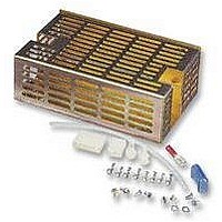
COVER KIT, NFS40
Manufacturer
ARTESYN
Datasheet
1.NFS110COVERKITJ.pdf
(3 pages)
Specifications of NFS40COVERKITJ
Enclosure Type
Power Supply
External Depth
30mm
External Length / Height
127mm
External Width
81mm
Ip/nema Rating
RoHS Compliant
External Height - Metric
47.9mm
External Width - Metric
87.2mm
External Depth - Metric
139.5mm
Rohs Compliant
Yes


Cover Accessory Kits
NFS110
MODEL NUMBER: NFS110 COVER KIT
Bracket outside dim: 7.5” x 4.57” x 2.38” (190.5 x 116 x 60.5mm)
Cover outside dim: 7.5” x 4.51” x 2.32” (190.5 x 114.5 x 59mm)
•
•
•
•
The ‘NFS110 COVER KIT’ is manufactured in Europe with metric screw
threads and the kit includes assembly screws and installation instructions.
For the most current data and application support visit www.artesyn.com/powergroup/products.htm
LOW TO MEDIUM POWER AC/DC POWER SUPPLIES
MECHANICAL SPECIFICATIONS
NFS110
Assembly instructions
Mounting screws
Crimp terminals and mating connectors
0.24
(6.0)
See Note 8.
C
See Note 4.
B
A
(178.5)
7.01
(30.2)
1.19
(10.2)
0.41
A
A
C
C
B
(19.0)
0.75
A
(170.0)
6.69
(80.0)
3.15
A
A
C
Assembly Notes
1
2
3
4
5
6
7
8
9
Note:
responsibility to ensure that the requirements of the relevant safety agency, or
agencies, are satisfied.
Before assembly, ensure unit has been turned off for at least 10 minutes.
Cover cable exit area with grommet strip provided (optional). Not required
for the NFS110.
Maximum screw penetration into customer mounting holes is 3mm.
Cover fuse with fuse cover provided.
“A” denotes customer M3 mounting holes.
“B” denotes PCB fixing screws.
“C” denotes case assembly points and screws.
Apply tape in location shown.
Dimensions are in inches (mm).
When a cover or other sheetmetal option is added, it is the user’s
File Name: NFS_COVER_KITS.PDF Rev: 08 Oct 2002
www.artesyn.com
2