TCMD1000 Vishay, TCMD1000 Datasheet - Page 3
TCMD1000
Manufacturer Part Number
TCMD1000
Description
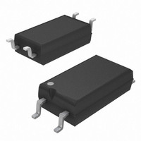
Optocoupler
Manufacturer
Vishay
Datasheet
1.TCMD1000.pdf
(7 pages)
Specifications of TCMD1000
Leaded Process Compatible
Yes
Peak Reflow Compatible (260 C)
No
Number Of Channels
1
Input Type
DC
Voltage - Isolation
3750Vrms
Current Transfer Ratio (min)
600% @ 1mA
Voltage - Output
35V
Current - Output / Channel
80mA
Current - Dc Forward (if)
60mA
Vce Saturation (max)
1V
Output Type
Darlington
Mounting Type
Surface Mount
Package / Case
4-SOP
Maximum Input Diode Current
60 mA
Maximum Reverse Diode Voltage
6 V
Output Device
Darlington
Configuration
1
Maximum Collector Emitter Voltage
35 V
Maximum Collector Emitter Saturation Voltage
1000 mV
Isolation Voltage
3750 Vrms
Current Transfer Ratio
800 % (Typ)
Maximum Forward Diode Voltage
1.6 V
Maximum Collector Current
80 mA
Maximum Power Dissipation
250 mW
Maximum Operating Temperature
+ 100 C
Minimum Operating Temperature
- 40 C
Number Of Elements
1
Reverse Breakdown Voltage
6V
Forward Voltage
1.6V
Forward Current
60mA
Collector-emitter Voltage
35V
Package Type
Mini Flat
Collector Current (dc) (max)
80mA
Power Dissipation
250mW
Collector-emitter Saturation Voltage
1V
Pin Count
4
Mounting
Surface Mount
Operating Temp Range
-40C to 100C
Operating Temperature Classification
Industrial
Lead Free Status / RoHS Status
Lead free / RoHS Compliant
Current Transfer Ratio (max)
-
Lead Free Status / Rohs Status
Lead free / RoHS Compliant
Available stocks
Company
Part Number
Manufacturer
Quantity
Price

Part Number:
TCMD1000V103U27
Manufacturer:
VISHAY/威世
Quantity:
20 000


TYPICAL CHARACTERISTICS (T
Document Number: 83513
Rev. 2.1, 09-Feb-11
R
t
T
0
p
t
14779
G
p
14389
Fig. 3 - Forward Voltage vs. Ambient Temperature
14390
= 0.01
= 50 s
= 50 Ω
Fig. 1 - Test Circuit, Non-Saturated Operation
Fig. 4 - Forward Current vs. Forward Voltage
1000
100
1.3
1.2
1.1
1.0
0.9
0.8
0.1
I
10
F
1
0.0
50 Ω
0
I
F
T
0.4
amb
20
V
- Ambient Temperature (°C)
F
- Forward Voltage (V)
R
0.8
40
L
+ V
I
C
For technical questions, contact:
Channel I
Channel II
= 10 mA
1.2
60
CC
I
F
= 10 mA
amb
1.6
80
Output, High Gain, Single/Quad
Optocoupler, Photodarlington
Channel, Half Pitch Mini-Flat
Oscilloscope
R I = 1 MΩ
C I = 20 pF
= 25 °C, unless otherwise specified)
100
2.0
optocoupleranswers@vishay.com
Fig. 6 - Collector Dark Current vs. Ambient Temperature
t
t
t
t
p
d
r
on
14391
14392
(= t
100 000
100 %
10 000
90 %
10 %
d
1000
+ t
I
I
100
C
Fig. 5 - Relative Current Transfer Ratio vs.
F
1.5
1.4
1.3
1.2
1.1
1.0
0.9
0.8
0.7
0.6
0.5
0
0
10
r
- 30 - 20 - 10 0 10 20 30 40 50 60 70 80 90 100
)
1
20
TCMD1000, TCMD4000
t
Pulse duration
Delay time
Rise time
Turn-on time
d
V
I
t
V
F
30
on
CE
CE
t
Fig. 2 - Switching Times
= 1 mA
r
I
T
T
Ambient Temperature
F
amb
= 5 V
amb
= 10 V
= 0
40
Vishay Semiconductors
t
- Ambient Temperature (°C)
- Ambient Temperature (°C)
p
50
60
t
t
t
t
s
f
off
s
(= t
70
s
t
off
+ t
t
f
f
80
)
90 100
Storage time
Fall time
Turn-off time
www.vishay.com
96 11698
t
t
3
Related parts for TCMD1000
Image
Part Number
Description
Manufacturer
Datasheet
Request
R

Part Number:
Description:
357-036-542-201 CARDEDGE 36POS DL .156 BLK LOPRO
Manufacturer:
Vishay
Datasheet:
Part Number:
Description:
357-036-542-201 CARDEDGE 36POS DL .156 BLK LOPRO
Manufacturer:
Vishay
Datasheet:
Part Number:
Description:
357-036-542-201 CARDEDGE 36POS DL .156 BLK LOPRO
Manufacturer:
Vishay
Datasheet:
Part Number:
Description:
357-036-542-201 CARDEDGE 36POS DL .156 BLK LOPRO
Manufacturer:
Vishay
Datasheet:
Part Number:
Description:
357-036-542-201 CARDEDGE 36POS DL .156 BLK LOPRO
Manufacturer:
Vishay
Datasheet:
Part Number:
Description:
357-036-542-201 CARDEDGE 36POS DL .156 BLK LOPRO
Manufacturer:
Vishay
Datasheet:
Part Number:
Description:
357-036-542-201 CARDEDGE 36POS DL .156 BLK LOPRO
Manufacturer:
Vishay
Datasheet:
Part Number:
Description:
357-036-542-201 CARDEDGE 36POS DL .156 BLK LOPRO
Manufacturer:
Vishay
Datasheet:
Part Number:
Description:
357-036-542-201 CARDEDGE 36POS DL .156 BLK LOPRO
Manufacturer:
Vishay
Datasheet:
Part Number:
Description:
357-036-542-201 CARDEDGE 36POS DL .156 BLK LOPRO
Manufacturer:
Vishay
Datasheet:
Part Number:
Description:
357-036-542-201 CARDEDGE 36POS DL .156 BLK LOPRO
Manufacturer:
Vishay
Datasheet:
Part Number:
Description:
357-036-542-201 CARDEDGE 36POS DL .156 BLK LOPRO
Manufacturer:
Vishay
Datasheet:
Part Number:
Description:
357-036-542-201 CARDEDGE 36POS DL .156 BLK LOPRO
Manufacturer:
Vishay
Datasheet:
Part Number:
Description:
357-036-542-201 CARDEDGE 36POS DL .156 BLK LOPRO
Manufacturer:
Vishay
Datasheet:
Part Number:
Description:
357-036-542-201 CARDEDGE 36POS DL .156 BLK LOPRO
Manufacturer:
Vishay
Datasheet: