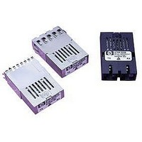
HFBR-5208EM Avago Technologies US Inc., HFBR-5208EM Datasheet - Page 5

HFBR-5208EM
Manufacturer Part Number
HFBR-5208EM
Description
Fiber Optics, Transceiver Module
Manufacturer
Avago Technologies US Inc.
Specifications of HFBR-5208EM
Peak Reflow Compatible (260 C)
No
Leaded Process Compatible
No
Connector Type
SC Duplex
Lead Free Status / RoHS Status
Contains lead / RoHS non-compliant
Operation in -5.2 V Designs
For applications that require -5.2 V dc power supply level
for true ECL logic circuits, the HFBR/HFCT-5208M transceiver
can be operated with a V
This transceiver is not specified with an operating, negative
power supply voltage. The potential compromises that can
occur with use of -5.2 V dc power are that the absolute
voltage states for V
to the 0.2 V difference in supply levels. Also, noise immunity
may be compromised for the HFBR/HFCT-5208M trans-
ceiver because the ground plane is now the V
point. The suggested power supply filter circuit shown in
the Recommended Circuit Schematic figure should be
located in the V
coupling of the differential data signal can be done between
the HFBR-5208M transceiver and the standard ECL circuits.
For guaranteed -5.2 V dc operation, contact your local
Avago Technolgies Component Field Sales Engineer for
assistance.
(0.800)
Figure 5. Recommended Board Layout Pattern
Figure 6. 622.08 Mb/s OC-12 ATM-SONET/SDH Reference Design Board
5
20.32
(0.100)
2.54
EE
paths at the transceiver supply pins. Direct
OH
(0.800)
20.32
and V
CC
OL
= 0 V dc and a V
will be changed slightly due
TOP VIEW
2 x
(0.075 – 0.004)
9 x
(0.032 – 0.004)
1.9 – 0.1
EE
0.8 – 0.1
= -5.2 V dc.
CC
supply
Electromagnetic Interference (EMI)
One of a circuit board designer’s foremost concerns is the
control of electromagnetic emissions from electronic
equipment.
Electromagnetic Interference (EMI) enables the designer to
pass a governmental agency’s EMI regulatory standard; and
more importantly, it reduces the possibility of interference
to neighboring equipment. There are three options
available for the HFBR/HFCT-5208M with regard to EMI
shielding for providing the designer with a means to
achieve good EMI performance. The EMI performance of
an enclosure using these transceivers is dependent on the
chassis design. Avago Technolgies encourages using
standard RF suppression practices and avoiding poorly EMI-
sealed enclosures. In addition, Avago Technolgies advises
that for the best EMI performance, the metalized case must
be connected to chassis ground using one of the shield
options.
HFBR/HFCT-5208EM transceiver beyond the front surface
of the panel or enclosure is 6.35 mm (0.25 in) . With this
option, there is flexibility of positioning the module to fit
the specific need of the enclosure design. (See Figure 8 for
the mechanical drawing dimensions of this shield.)
The second shielded option, option FM, is for applications
that are designed to have a flush mounting of the module
with respect to the front of the panel or enclosure. The
flush-mount design accommodates a large variety of panel
thickness, i.e. 1.02 mm (.04 in) min to 2.54 mm (0.1 in)
max. Note the reference plane for the flush-mount design
is the interior side of the panel or enclosure. The
recommended distance from the centerline of the
transceiver front solder posts to the inside wall of the panel
is 13.82 mm (0.544 in) . This option contacts the inside
panel or enclosure wall on all four sides of this metal shield.
(See Figure 10 for the mechanical drawing dimensions of
this shield.)
Success
in
controlling
generated


