HFBR-1414 Avago Technologies US Inc., HFBR-1414 Datasheet - Page 10
HFBR-1414
Manufacturer Part Number
HFBR-1414
Description
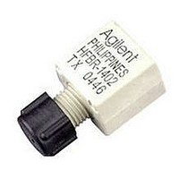
Fiber Optics, Transceiver Module
Manufacturer
Avago Technologies US Inc.
Datasheet
1.HFBR-1414.pdf
(24 pages)
Specifications of HFBR-1414
Data Rate Max
115Kbps
Peak Reflow Compatible (260 C)
No
Leaded Process Compatible
No
Lead Free Status / RoHS Status
Contains lead / RoHS non-compliant
Available stocks
Company
Part Number
Manufacturer
Quantity
Price

Part Number:
HFBR-1414
Manufacturer:
HP
Quantity:
20 000
Company:
Part Number:
HFBR-1414MZ
Manufacturer:
Avago Technologies US Inc.
Quantity:
135
Company:
Part Number:
HFBR-1414MZ
Manufacturer:
MINI
Quantity:
5 000
Part Number:
HFBR-1414T
Manufacturer:
HP
Quantity:
20 000
Company:
Part Number:
HFBR-1414TZ
Manufacturer:
TI
Quantity:
5 560
Company:
Part Number:
HFBR-1414TZ
Manufacturer:
Avago Technologies US Inc.
Quantity:
1 871
Part Number:
HFBR-1414TZ
Manufacturer:
AVAGO/安华高
Quantity:
20 000


5 MBd Logic Link Design
If resistor R
70.4 , a forward current I
48 mA is applied to the HFBR-
14X4 LED transmitter. With I
48 mA the HFBR-14X4/24X2
logic link is guaranteed to work
with 62.5/125 m fiber optic
cable over the entire range of 0
to 1750 meters at a data rate of
dc to 5 MBd, with arbitrary data
format and pulse width distortion
typically less than 25%. By
setting R
ter can be driven with I
if it is desired to economize on
power or achieve lower pulse
distortion.
Figure 2. Typical circuit configuration.
10
1
= 115
1
in Figure 2 is
, the transmit-
F
= 30 mA,
F
of
F
=
The following example will illus-
trate the technique for selecting
the appropriate value of I
Maximum distance required
= 400 meters. From Figure 3 the
drive current should be 15 mA.
From the transmitter data
V
as shown in Figure 9.
R
R
F
1
1
= 1.5 V (max.) at I
= ––––––– = –––––––––
= 233
V
CC
I
F
- V
F
5 V - 1.5 V
15 mA
F
= 15 mA
F
and R
1
.
The curves in Figures 3, 4, and 5
are constructed assuming no in-
line splice or any additional
system loss. Should the link
consists of any in-line splices,
these curves can still be used to
calculate link limits provided they
are shifted by the additional
system loss expressed in dB. For
example, Figure 3 indicates that
with 48 mA of transmitter drive
current, a 1.75 km link distance
is achievable with 62.5/125 m
fiber which has a maximum
attenuation of 4 dB/km. With
2 dB of additional system loss, a
1.25 km link distance is still
achievable.
Related parts for HFBR-1414
Image
Part Number
Description
Manufacturer
Datasheet
Request
R

Part Number:
Description:
FIBER OPTIC CBL SIMPLEX 1=100M
Manufacturer:
Avago Technologies US Inc.
Datasheet:

Part Number:
Description:
FIBER OPTIC CBL SIMPLEX 1=500M
Manufacturer:
Avago Technologies US Inc.
Datasheet:

Part Number:
Description:
FIBER OPTIC CONN LATCH GRY SIMPL
Manufacturer:
Avago Technologies US Inc.
Datasheet:

Part Number:
Description:
FIBER OPTIC CONN LATCH BLU SIMPL
Manufacturer:
Avago Technologies US Inc.
Datasheet:

Part Number:
Description:
XMITTER VERSATILE LINK HORZ
Manufacturer:
Avago Technologies US Inc.
Datasheet:

Part Number:
Description:
Fiber Optic Transmitters, Receivers, Transceivers 1300nm 155MBd 16-pin DIP ST Rx
Manufacturer:
Avago Technologies US Inc.

Part Number:
Description:
FIBER OPTIC CBL DUPLEX 1=100M
Manufacturer:
Avago Technologies US Inc.
Datasheet:
Part Number:
Description:
FIBER OPTIC CBL SIMPLEX 1=500M
Manufacturer:
Avago Technologies US Inc.
Datasheet:
Part Number:
Description:
FIBER OPTIC CBL DUPLEX 1=500M
Manufacturer:
Avago Technologies US Inc.
Datasheet:

Part Number:
Description:
FIBER OPTIC CBL SIMPLEX 1=100M
Manufacturer:
Avago Technologies US Inc.
Datasheet:

Part Number:
Description:
OPTOCOUPLER GATE DRV 2A 16-SOIC
Manufacturer:
Avago Technologies US Inc.
Datasheet:
Part Number:
Description:
OPTOCOUPLER 2CH 2.5A 16-SOIC
Manufacturer:
Avago Technologies US Inc.
Datasheet:

Part Number:
Description:
OPTOCOUPLER GATE DRV 0.4A 16SOIC
Manufacturer:
Avago Technologies US Inc.
Datasheet:

Part Number:
Description:
OPTOCOUPLER 2.0A 250KHZ 8-DIP
Manufacturer:
Avago Technologies US Inc.
Datasheet:

Part Number:
Description:
OPTOCOUPLER 2.0A 250KHZ GW 8-SMD
Manufacturer:
Avago Technologies US Inc.
Datasheet: