HFBR-0501Z Avago Technologies US Inc., HFBR-0501Z Datasheet - Page 8
HFBR-0501Z
Manufacturer Part Number
HFBR-0501Z
Description
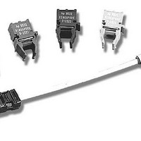
DC-5MBd 650nm POF Eval Kit
Manufacturer
Avago Technologies US Inc.
Specifications of HFBR-0501Z
Mfg Application Notes
Versatile Link AppNote
Main Purpose
Interface, Fiber Optics
Embedded
No
Utilized Ic / Part
HFBR-1521Z, HFBR-2521Z
Primary Attributes
650nm, 5MBd, POF
Operating Voltage
5 V
Description/function
Versatile Fiber Optic Evaluation Kit
Maximum Operating Temperature
+ 85 C
Minimum Operating Temperature
- 40 C
Operating Current
6.2 mA
Leaded Process Compatible
Yes
Rohs Compliant
Yes
Peak Reflow Compatible (260 C)
Yes
Lead Free Status / RoHS Status
Lead free / RoHS Compliant
Secondary Attributes
-
Lead Free Status / Rohs Status
Details
For Use With/related Products
HFBR-1521Z, HFBR-2521Z
Lead Free Status / RoHS Status
Lead free / RoHS Compliant
Other names
516-2315


Transmitter Electrical/Optical Characteristics
Notes:
1. Measured at the end of 0.5 m standard fiber optic cable with large area detector.
2. Optical power, P (dBm) = 10 Log [P(μW)/1000 μW].
3. Rise and fall times are measured with a voltage pulse driving the transmitter and a series connected 50 Ω load. A wide bandwidth optical to
8
Figure 9. Typical forward voltage vs. drive current
Parameter
Transmitter Output
Output Optical Power
Temperature Coefficient
Peak Emission
Wavelength
Forward Voltage
Forward Voltage
Temperature Coefficient
Effective Diameter
Numerical Aperture
Reverse Input Breakdown
Voltage
Diode Capacitance
Rise Time
Fall Time
Optical Power
electrical waveform analyzer, terminated to a 50 Ω input of a wide bandwidth oscilloscope, is used for this response time measurement.
1.8
1.7
1.6
1.5
1.4
2
I
Fdc
– TRANSMITTER DRIVE CURRENT (mA)
10
0°C
25°C
70°C
100
ΔV
Symbol
ΔP
O
V
NA
C
P
T
V
F
D
t
t
PK
BR
F
O
r
T
/ΔT
/ΔT
f
0°C to 70°C unless otherwise specified.
-16.5
-14.3
Min.
1.45
5.0
Typ.
-0.85
-1.37
1.67
11.0
660
0.5
86
80
40
1
[5]
Figure 10. Normalized typical output power vs. drive current
-10
-15
-20
-5
5
0
Max.
2.02
2
-7.6
-8.0
I
Fdc
– TRANSMITTER DRIVE CURRENT (mA)
mV/°C
Units
%/°C
dBm
dBm
mm
nm
pF
ns
ns
V
V
10
I
I
I
I
T
V
10% to 90%,
I
Fdc
Fdc
Fdc
Fdc
A
F
F
= 60 mA
= 25°C
= 0, f = MHz
= 60 mA
= 60 mA, 25°C
= 60 mA
= 10 μA,
Conditions
100
Notes 1, 2
Note 3
Fig. 9
Ref.
Related parts for HFBR-0501Z
Image
Part Number
Description
Manufacturer
Datasheet
Request
R

Part Number:
Description:
Fiber Optic Transmitters, Receivers, Transceivers 1300nm 155MBd 16-pin DIP ST Rx
Manufacturer:
Avago Technologies US Inc.

Part Number:
Description:
FIBER OPTIC TX 125 MBD 650N
Manufacturer:
Avago Technologies US Inc.
Datasheet:

Part Number:
Description:
Fiber Optic Evaluation Kit
Manufacturer:
Avago Technologies US Inc.
Datasheet:

Part Number:
Description:
RECEIVER FIBER OPTIC ST 266MBD
Manufacturer:
Avago Technologies US Inc.
Datasheet:

Part Number:
Description:
RCVR OPT HI SPEED VERS LINK HORZ
Manufacturer:
Avago Technologies US Inc.
Datasheet:

Part Number:
Description:
RCVR OPT HI SPEED VERS LINK VERT
Manufacturer:
Avago Technologies US Inc.
Datasheet:

Part Number:
Description:
TXRX OPTICAL 850NM VCSEL MT-RJ
Manufacturer:
Avago Technologies US Inc.
Datasheet:

Part Number:
Description:
TXRX MM SFP LC CONN BAIL DELATCH
Manufacturer:
Avago Technologies US Inc.
Datasheet:

Part Number:
Description:
TXRX MMF SFP GBE/FC BAIL DELATCH
Manufacturer:
Avago Technologies US Inc.
Datasheet:

Part Number:
Description:
XMITTER FIBER OPTIC 266MBD ST
Manufacturer:
Avago Technologies US Inc.
Datasheet:

Part Number:
Description:
OPTOCOUPLER GATE DRV 2A 16-SOIC
Manufacturer:
Avago Technologies US Inc.
Datasheet:
Part Number:
Description:
OPTOCOUPLER 2CH 2.5A 16-SOIC
Manufacturer:
Avago Technologies US Inc.
Datasheet:

Part Number:
Description:
OPTOCOUPLER GATE DRV 0.4A 16SOIC
Manufacturer:
Avago Technologies US Inc.
Datasheet:

Part Number:
Description:
OPTOCOUPLER 2.0A 250KHZ 8-DIP
Manufacturer:
Avago Technologies US Inc.
Datasheet:

Part Number:
Description:
OPTOCOUPLER 2.0A 250KHZ GW 8-SMD
Manufacturer:
Avago Technologies US Inc.
Datasheet: